

Description
- Brand: Fireye
- GE Website Classification: Industrial flame monitoring component
- Full Model Number: 85UVF1A-1QDK3
- System/Series Family: Phoenix Series 85UVF Flame Scanner
- Core Function: Microprocessor-based ultraviolet flame detection with integrated flame and fault relays
- Top 3 Hardcore Specs: 24 VDC nominal supply | 4-20 mA isolated analog output | 8-pin quick-disconnect
- Detection Type: UV solid-state sensor
- Housing: Cast aluminum
- Protection: IP66
- Stock Status: New surplus, factory sealed, or fully tested refurbished subject to exact inventory confirmation
The 85UVF1A-1QDK3 is a Fireye Phoenix Series 85UVF integrated UV flame scanner, not a GE Multilin protection relay or conventional GE control module. Fireye documentation lists this exact model among the Phoenix scanners, with FM, UL C/US, CE, Class I Division 2, NEMA 4X, and IP66 approvals shown in the applicable approval table.
Module 3: Technical Product Introduction
A flame scanner failure is a burner-management problem first and a spare-parts problem second. The Fireye 85UVF1A-1QDK3 provides ultraviolet flame detection using a solid-state sensor and incorporates internal flame and fault relays, allowing the scanner to provide both flame-status and fault information directly to the burner-management system. The 1QD configuration uses an 8-pin quick-disconnect connection, while the K3 designation identifies the specific optical-filter configuration.
The electrical and environmental specifications are equally important during replacement. Published technical data specifies 24 VDC nominal input power, approximately 200 mA supply current, a 4-20 mA optically isolated analog output, and IP66 protection. The scanner is rated for an ambient temperature range of approximately -40°C to +65°C, with an internal scanner temperature limit of approximately 82°C. The flame and fault relay contacts are rated up to 2 A at 230 VAC resistive load.
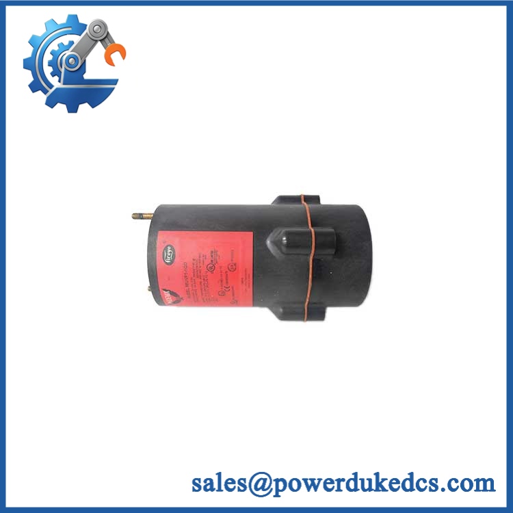
GE 85UVF1A-1QDK3
Module 4: Application Scenarios & Field Realities
- On industrial burners and fired equipment, the 85UVF1A-1QDK3 provides continuous UV-based flame supervision. Correct sighting is critical; a scanner that sees refractory glow, adjacent burners, or unwanted background radiation can produce a misleading flame signal even when the electronics are functioning normally.
- For refinery, power-generation, and process-heating applications, the K3-filter configuration can be relevant where the optical characteristics of the combustion environment require a particular spectral response. Confirm the existing scanner’s complete suffix before substituting a standard 85UVF model.
- During burner maintenance outages, the quick-disconnect arrangement can simplify scanner removal while leaving the conduit arrangement undisturbed. Before replacement, record scanner orientation, sighting angle, cooling-air arrangement, cable type, and flame-signal behavior.
- Where hazardous-area certification matters, the exact scanner model and installation method must be checked together. Fireye’s approval documentation lists 85UVF1A-1QDK3 with multiple agency approvals, including FM, UL C/US, CE, Class I Division 2, NEMA 4X, and IP66.
Module 5: Migration, Compatibility & Installation Traps
Replacement Matrix
| Replacement Type | Assessment | Engineering Requirement |
|---|---|---|
| Drop-in Replacement | Potentially yes for an identical 85UVF1A-1QDK3 installation | Match scanner model, optical filter, connection type, mounting arrangement, and certification |
| Software Compatible | Configuration-dependent | Verify FFRT, flame-signal settings, burner-management logic, and analog-output scaling |
| Hardware Modification Required | Potentially required when replacing an older scanner generation | Confirm mounting flange, cable, sighting tube, and cooling-air arrangement |
Field Traps — Watch Out
1. K3 filter is part of the identification: The 85UVF1A-1QDK3 should not automatically be replaced with 85UVF1A-1QD or another Phoenix 85-series scanner. Fireye’s documentation lists these as separate models, and the K3 configuration has its own optical characteristics.
2. Mounting hardware may change during migration: Secondary technical documentation identifies the 60-2919-1 mounting flange for this scanner configuration and notes a 1-inch NPT female pipe connection with a 3/8-inch NPT cooling-air connection. If replacing an older scanner, verify the complete mechanical interface before installation.
3. Cooling air is not optional: The published installation data specifies clean, dry, cool air, with approximately 4 SCFM / 113 L/min through the applicable cooling connection. Insufficient cooling can raise the internal scanner temperature even when the surrounding furnace area appears acceptable.
4. Flame sighting must be recommissioned: After physical replacement, verify the actual flame signal under operating conditions. Do not assume that aligning the new scanner to the same mechanical position guarantees the same optical signal.
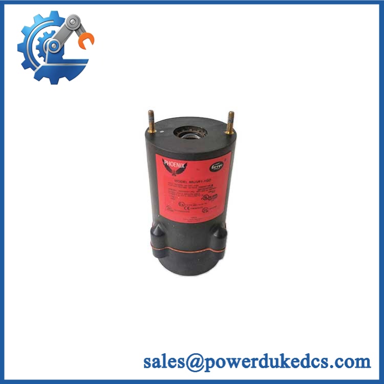
GE 85UVF1A-1QDK3
Module 6: Quality Assurance SOP
Before shipment, each 85UVF1A-1QDK3 should undergo a documented inspection sequence appropriate to the available Fireye Phoenix test equipment.
- Step 1 — Part-number verification: Record 85UVF1A-1QDK3, serial number, manufacturing information, housing identification, and all visible Fireye/Phoenix markings.
- Step 2 — OEM anti-counterfeit visual inspection: Inspect the Fireye label, model code, enclosure markings, connector assembly, optical window, mounting interface, fasteners, and manufacturing identifiers. Photograph the complete nameplate.
- Step 3 — Physical condition inspection: Check the cast-aluminum housing, optical window, connector, mounting threads, flange interface, and enclosure for corrosion, cracks, impact damage, contamination, or evidence of previous repair.
- Step 4 — Power-supply verification: Confirm a controlled 24 VDC nominal test supply and verify polarity before energizing the scanner. Record the measured supply voltage and current behavior.
- Step 5 — Power-on self-test (POST): Energize the scanner under controlled conditions and verify startup diagnostics, LED indications, flame-status indication, and fault-status behavior.
- Step 6 — UV detection verification: Use an appropriate calibrated flame or UV test source to verify that the scanner detects the intended UV signal and responds correctly when the source is removed.
- Step 7 — Flame relay verification: Exercise the internal flame relay and verify the expected SPST normally-open contact behavior.
- Step 8 — Fault relay verification: Trigger the applicable diagnostic condition and confirm operation of the SPST normally-closed fault relay.
- Step 9 — 4-20 mA verification: Apply representative flame-signal conditions and verify the optically isolated 4-20 mA output across suitable test points. Confirm the receiving-load requirement does not exceed the specified 750 Ω maximum.
- Step 10 — Final photographic record: Photograph the complete scanner, model label, optical head, connector, mounting interface, and final packaging.
QA release criterion: A successful power-up is not sufficient to classify the scanner as fully tested. The inspection record should distinguish visual inspection, electrical testing, flame-detection testing, relay testing, and 4-20 mA output verification. For a safety-related burner application, final installation and functional verification must follow the site’s approved burner-management procedure and the applicable Fireye documentation.











 Start Chat


