

Description
- Model: GE DS200DPCBG1AAA
- Brand: GE / General Electric
- Series: Mark V DS200
- Part Type: IOS+ Power Connect Board
- Functional Acronym: DPCB
- Core Function: Provides power and signal connection functions within the GE Mark V turbine-control architecture.
- Key Hardware: Two wire terminal blocks supporting up to six signal wires, one onboard fuse, and one toggle switch. The documented assembly is normal coating, with functional revisions A/A and artwork revision A.
Product Introduction
A Mark V cabinet can remain electrically serviceable for years while a small power-interface PCB develops a connector, fuse, or switching fault. The GE DS200DPCBG1AAA is identified as an IOS+ Power Connect Card within the Mark V DS200 family, where its role is centered on power connection and signal interfacing rather than turbine sequencing or processor control.
Physically, the board carries two wire terminal blocks, provision for up to six signal conductors, an onboard fuse, and a toggle switch. GE’s legacy Mark V numbering is revision-specific: this unit is recorded as DPCB, normal coating, first functional revision A, second functional revision A, and artwork revision A. Those markings should remain attached to the inventory record (especially when old and later DS200 variants coexist in the same cabinet).
Core Technical Specifications
| Parameter | Value |
|---|---|
| Manufacturer | GE / General Electric |
| Catalog Number | DS200DPCBG1AAA |
| Product Family | Mark V DS200 |
| Functional Description | IOS+ Power Connect Card |
| Functional Acronym | DPCB |
| Primary Role | Power connection and signal interface |
| Terminal Blocks | 2 wire terminal blocks |
| Signal Capacity | Up to 6 signal wires |
| Fuse | 1 onboard fuse |
| Local Switching | 1 toggle switch |
| PCB Coating | Normal coating |
| Functional Revision 1 | A |
| Functional Revision 2 | A |
| Artwork Revision | A |
| Board Type | Printed circuit board assembly |
| Reported Board Size | Approximately 6.25 × 5 in |
| Board Mounting | Four corner mounting holes reported |
| Processor | Not applicable as a dedicated CPU board |
| User Memory | None documented for this board |
| Standalone Firmware | None documented |
| Exact Power Rating | Not reliably established in the public records reviewed |
| Exact Heat Dissipation | Not reliably established |
| Exact Operating Temperature | Not reliably established |
| Lifecycle | Legacy / obsolete Mark V hardware |
The board’s identification, terminal arrangement, fuse, toggle switch, coating, revision structure, and approximate 6.25 × 5 inch physical size are supported by specialist Mark V parts records.
An important engineering limitation remains: the publicly available material does not provide a sufficiently reliable OEM electrical specification for the board’s input voltage, output voltage, current capacity, or thermal dissipation. Those values should therefore be taken from the specific Mark V cabinet documentation rather than inferred from unrelated DS200 boards.
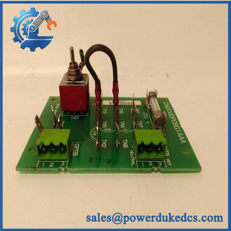
GE DS200DPCBG1AAA
Application Scenarios & Pain Points
Micro-case — cabinet power-interface fault: A Mark V cabinet develops an intermittent control-power or signal-connection problem, while the main controller remains operational. After checking the external supply and field wiring, the DPCB becomes a candidate for board-level replacement.
Within turbine-control cabinets, the DS200DPCBG1AAA is used as a power-connect and signal-interface board rather than as a processor. Its two terminal blocks accommodate up to six signal wires, making connector condition a practical maintenance concern.
For legacy Mark V installations, the single onboard fuse provides overcurrent protection for the board. GE-oriented maintenance records specifically warn that the replacement fuse must have the same rating as the original rather than being substituted with a higher-current device.
In cabinets with undocumented modifications, the toggle switch and terminal wiring deserve special attention. Photograph the board before removal; field changes can otherwise be mistaken for an original factory configuration.
At 50°C+ ambient temperatures, inspect the fuse area, terminal blocks, switch, solder joints, and nearby components for thermal discoloration. An exact continuous operating-temperature specification for this board was not verified in the public documentation reviewed.
🚨 Common Error Codes & Diagnostic Symptoms
No reliable GE service source located for DS200DPCBG1AAA establishes a universal numerical fault-code list. The following are physical or system-level diagnostic symptoms.
Symptom/Code: Board-associated power or signal path unavailable → Diagnosis: Possible open fuse, poor terminal contact, damaged conductor, toggle-switch fault, or PCB-level connection problem → Action: Isolate the external wiring and supply first, then replace the DPCB when the fault is demonstrated at board level.
Symptom/Code: Intermittent signal loss after cabinet vibration or maintenance → Diagnosis: Loose terminal hardware, degraded solder joints, connector stress, or mechanical movement around the board can create intermittent continuity → Action: Inspect both terminal blocks and mounting points, then substitute a verified board when the fault follows the assembly.
Symptom/Code: Fuse repeatedly opens after replacement → Diagnosis: A downstream short, excessive current, damaged component, or external wiring problem may be present; the fuse is acting as protection rather than identifying the root cause → Action: Do not increase the fuse rating; locate the overcurrent source and replace the board only after the external fault has been eliminated.
🚨 Cross-Reference & Lifecycle Migration
Exact Identity
GE DS200DPCBG1AAA = Mark V IOS+ Power Connect Card / DPCB.
Related DPC boards exist in the DS200 family, including DS200DPCAG1, DS200DPCAG1A, and DS200DPCBG1A. These related numbers should not be declared direct replacements simply because their descriptions contain “Power Connect” or because the mounting geometry appears similar. GE’s Mark V catalog contains multiple board functions under closely related DPC nomenclature.
Revision Control
The complete G1AAA suffix is important. Available records identify:
- Functional acronym: DPCB
- Functional revision 1: A
- Functional revision 2: A
- Artwork revision: A
- PCB coating: Normal
Do not drop the suffix when creating a purchase order or warehouse record.
Firmware Requirement
This board is a power/signal interface PCB, not a programmable controller. No independent user-firmware flashing procedure is documented for .
Replacement work therefore centers on exact hardware identity, terminal wiring, fuse specification, toggle-switch state, mounting, and the configuration of the host Mark V system.
Lifecycle Status
Lifecycle: Legacy / Obsolete.
The board belongs to the older Mark V Speedtronic control generation and is now principally encountered through specialist legacy-spares and repair channels. Current Mark V parts catalogs continue to list , while the product family itself is an established legacy architecture.
For critical turbine assets, buffer stock should be managed by exact part number and revision, not by the broad category “DPC power board.”
Field Engineer’s Tech Notes
First warning: do not install a larger fuse because the original blows. The onboard fuse is specifically intended to protect the board from excessive current, including transient conditions. GE-oriented maintenance guidance calls for a fuse with the same rating as the original.
Second warning: record the toggle-switch position before removal. The board has one toggle switch and two wire terminal blocks. A replacement with a changed switch state can create a confusing commissioning problem even when the PCB itself is healthy (especially on cabinets with limited documentation).
Use ESD protection during handling and support the PCB by its edges rather than the terminal blocks.
Strict QA & Testing SOP
1. Inbound identity verification
Confirm on the actual board. Record the DPCB acronym, A/A/A revision markings, serial/date information where present, and packaging condition.
2. Physical inspection
Inspect both terminal blocks, the fuse holder, toggle switch, mounting holes, PCB surface, solder joints, and connector interfaces for damage, corrosion, contamination, or prior repair.
3. Configuration documentation
Photograph the terminal wiring and the toggle-switch state before the board enters testing.
4. Fuse verification
Confirm the installed fuse rating against the applicable Mark V documentation. Do not substitute a higher rating merely to prevent nuisance operation.
5. Continuity inspection
Perform controlled continuity checks across the applicable signal and power paths before energization.
6. Controlled power test
Apply only the voltage specified by the host Mark V documentation for the exact installation. Monitor current and verify that the fuse remains intact.
7. Terminal verification
Exercise the applicable signal paths through the two terminal blocks and confirm stable continuity under controlled connection conditions.
8. Toggle-switch test
Verify the switch operates mechanically and electrically as intended by the host system configuration.
9. Load observation
Operate the board with a representative controlled load while monitoring fuse behavior, connection stability, and component temperature.
10. Extended observation
Check for intermittent open circuits, abnormal heating, terminal instability, or repeated fuse operation.
11. Final preservation
Place the board in ESD shielding protection, secure the terminal areas against impact, and retain the complete inspection record.
Test videos are available when live functional testing is performed and visual evidence is required for procurement approval.
Buyer’s FAQ
Is an I/O processor board?
No. It is identified as an IOS+ Power Connect Card, with the functional acronym DPCB. Its documented role is power connection and signal interfacing within the Mark V architecture.
Can I replace it with another DS200DPC board?
Not automatically. Related DPC boards exist, but similar catalog naming does not establish electrical equivalence. Verify the complete part number, revision, terminal arrangement, fuse specification, switch configuration, and host Mark V cabinet drawing first.
Can the board be hot-swapped?
Do not assume energized replacement is permitted. The board interfaces with cabinet power and signal circuits, and GE maintenance guidance calls for the drive/control equipment to be taken offline before board removal. Follow the applicable Mark V isolation and lockout procedure.
How do I verify New Original authenticity and warranty?
Request photographs of the actual , including the complete GE identification marking, DPCB, A/A/A revision information, fuse area, toggle switch, terminal blocks, and packaging. The purchase document should state New Original, New Surplus, refurbished, or repaired condition, together with the functional-test scope and warranty period.
For a controlled Mark V spare, retain + DPCB + A/A/A revision + fuse specification + switch state + terminal configuration + host-system reference + COO + QC result + packaging condition as one asset record.











 Start Chat


