

Description
- Model: DS200IIBDG1A
- Brand: GE / General Electric
- Series: Mark V DS200
- Part Type: AC2000 IGBT Gate Driver Board
- Core Function: Provides isolated gate-drive control for three-phase IGBT power devices while also handling motor-terminal voltage, current feedback, and fault-feedback isolation.
- Key Specifications: 6 optically isolated IGBT gate-driver circuits, two circuits per output phase, an onboard isolated power supply, phase current/voltage/fault feedback, 9 red status LEDs, and a factory-set J1 Berg-type jumper for gate turn-on delay.;
Product Introduction
The GE DS200IIBDG1A sits in the Mark V drive cabinet between low-power control circuitry and the IGBT power stage. Its six optically isolated driver circuits correspond to the upper and lower IGBTs for the three output phases. Separate feedback circuitry provides isolation for phase current, motor-terminal voltage, and fault information.
Internally, the IIBD board also contains isolation transformers and an internal supply for the gate-drive circuits and shunt-current-feedback voltage-controlled oscillator. The board carries nine red LEDs for operating-status indication and a manually movable J1 jumper associated with gate turn-on delay; that jumper is described as factory-set, so it should not be changed during routine replacement.
Core Technical Specifications
| Parameter | Value |
|---|---|
| Manufacturer | GE / General Electric |
| Product Family | Mark V DS200 |
| Exact Part Number | DS200IIBDG1A |
| Functional Acronym | IIBD |
| Product Type | AC2000 IGBT Gate Driver Board |
| PCB Coating | Normal coating |
| Functional Revision | A |
| IGBT Driver Circuits | 6 optically isolated circuits |
| Phase Allocation | 2 gate-drive circuits per output phase |
| Feedback Functions | Current, motor-terminal voltage, and fault feedback |
| Gate-Drive Isolation | Optical isolation |
| Internal Power Supply | Yes |
| Phase Isolation | Isolation transformers associated with each output phase |
| Status Indicators | 9 red LEDs |
| Jumper | J1, Berg-type, factory-set |
| J1 Function | Gate turn-on delay selection |
| Ribbon Interface | 32-pin ribbon-cable connector documented |
| Host Platform | GE Mark V / AC2000 drive architecture |
| Firmware | No independent application firmware identified |
| Board Dimensions | Approximate values vary by supplier; verify actual unit |
| Unit Weight | Approximately 0.45–0.58 kg in current secondary listings |
| Standalone Power Consumption | Not reliably established from OEM documentation |
| Standalone Heat Dissipation | Not reliably established |
| Operating Temperature | Exact OEM value not reliably established |
| Storage Temperature | Exact OEM value not reliably established |
| Mounting | Internal Mark V drive cabinet |
| Lifecycle | Legacy / obsolete |
The six-driver architecture, feedback functions, nine LEDs, J1 jumper, and 32-pin ribbon interface are supported by current technical records for the exact DS200IIBDG1A family.;
Published aftermarket mechanical data is inconsistent: one listing gives approximately 170 × 145 × 65 mm / 0.45 kg, another gives 280 × 80 × 25 mm / 0.58 kg. Because those envelopes conflict materially, neither should be used as a certified cabinet dimension. Verify the actual board and the Mark V cabinet drawing before mechanical planning.
Power and Thermal Note
No dependable OEM board-level wattage figure was established for the DS200IIBDG1A. This card is part of a much larger drive power-control system, so thermal performance depends on the host drive, switching activity, adjacent boards, airflow, and cabinet temperature.
Do not use generic internet values such as 24 VDC, 100 W, or 600 V as the board’s own engineering rating unless the applicable GE documentation confirms that figure for the exact assembly. Several current listings mix drive-level characteristics with board-level specifications.
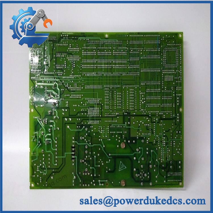
GE DS200IIBDG1A
Application Scenarios & Pain Points
A Mark V AC2000 drive develops an intermittent power-stage fault after prolonged operation. The IIBD board is a logical inspection point when the drive’s gate-control path, feedback isolation, or fault-feedback circuits are suspected. Its function directly connects the low-voltage control electronics with the IGBT switching stage.
For three-phase motor-drive applications, the six isolated gate-driver circuits support the upper and lower IGBTs across all three output phases. Current and voltage feedback are separately isolated, allowing the control system to monitor the power stage.
During legacy Mark V maintenance, the board’s connector routing deserves as much attention as its electronics. GE-related service instructions specify reconnecting cables to their original connector positions, and the 32-pin ribbon cable uses retention tabs that must be released correctly.
For turbine drive cabinets in hot environments, a 50°C+ internal ambient should trigger inspection of cabinet fans, air filters, adjacent power boards, and cooling paths before blaming the IIBD card for intermittent operation.
🚨 Common Error Codes & Diagnostic Symptoms
The DS200IIBDG1A is a board-level drive component, not a standalone intelligent module with a dedicated software fault-code database. Most diagnostic evidence originates from the Mark V host system and the board’s status indicators.
Symptom/Code: Gate-drive-related drive fault / repeated inverter shutdown → Diagnosis: Possible causes include failed isolated driver circuitry, loss of the internal driver supply, connector problems, or a fault in the associated IGBT power stage. → Action: Isolate the power stage and verify the surrounding drive circuitry before replacing the IIBD board.
Symptom/Code: Abnormal current or voltage feedback from one phase → Diagnosis: A failure in the corresponding feedback-isolation circuit, wiring, connector, or downstream sensing path can produce phase-specific measurement errors. → Action: Compare the affected phase with the other two phases and replace the board if the fault follows the IIBD assembly.
Symptom/Code: Abnormal 9-LED status pattern → Diagnosis: The nine red LEDs provide local indication of board activity, but their meaning depends on the exact board documentation and operating state. → Action: Record the LED pattern before resetting or removing the card, then correlate it with the Mark V diagnostic procedure.
🚨 Cross-Reference & Lifecycle Migration
The principal family references are:
- — AC2000 IGBT Gate Driver Board.
- DS200IIBDG1 — base IIBD functional family.
- DS200IIBDG1AGA — a separately identified variant with the same broad IGBT gate-driver function but a different hardware suffix.
These numbers should not be treated as automatic drop-in equivalents. The AGA variant, for example, has a different documented connector arrangement: three 8-pin connectors labeled APL/BPL/CPL plus a 34-pin ribbon connector, rather than the connector description documented for the .
The exact board suffix therefore belongs in the purchase order and warehouse master record. A visually similar IIBD board should not be issued until connector layout, revision, jumper configuration, and host-drive application have been confirmed.
Previous Revision / Hardware Relationship
DS200IIBDG1 is the base IIBD identifier, while carries functional revision A. Current specialist documentation identifies the A revision as the specific production configuration being offered.
No authoritative evidence was found establishing that every earlier DS200IIBDG1 or later IIBD suffix is a direct substitute for .
Firmware
No standalone field firmware procedure was established for the . This board implements gate-drive and feedback circuitry as hardware.
Application compatibility is therefore governed primarily by board revision, connector arrangement, J1 configuration, host-drive design, and the associated IGBT power assembly.
Lifecycle Status
Legacy / obsolete. Current specialist inventories continue to list the exact board for repair and replacement, including unused and rebuilt stock, but the Mark V DS200 platform is a legacy-generation control architecture.
For buffer stock, retain the complete identity and the host-drive application. Do not consolidate multiple IIBD suffixes into one generic inventory number.
Field Engineer’s Tech Notes
Warning 1 — Do not alter J1 during routine replacement.
The documented J1 Berg-type jumper is factory-set and controls the specific gate turn-on delay. Photograph it before removal, then reproduce the original position exactly.
Warning 2 — Handle the ribbon cable by its connector body.
The 32-pin ribbon connector uses retention tabs. Pulling on the cable itself can damage fine conductors and create an intermittent signal path that looks like an electronic failure. Release both tabs, remove the connector straight, and label the cable before transfer.
Strict QA & Testing SOP
Step 1 — Exact identity inspection
Confirm , functional acronym IIBD, revision A, and all secondary board markings.
Step 2 — Mechanical inspection
Inspect the PCB, mounting points, terminal/interface areas, nine LEDs, jumper header, and connector housings for cracks, contamination, corrosion, or evidence of rework.
Step 3 — Connector inspection
Examine the 32-pin ribbon connector and other board interfaces for bent contacts, damaged retention tabs, oxidation, and mechanical stress.
Step 4 — J1 verification
Record the factory J1 position before testing. Do not rotate or relocate it merely to demonstrate adjustability.
Step 5 — ESD-controlled handling
Use grounded ESD precautions throughout unpacking, inspection, and installation.
Step 6 — Component screening
Where an authorized bench procedure is available, inspect the isolated gate-driver circuits, power-supply section, feedback paths, diodes, capacitors, and semiconductor components.
Step 7 — Low-risk electrical checks
Perform appropriate continuity, resistance, and isolation checks without applying arbitrary high voltage to semiconductor-connected paths.
Step 8 — Test-rig installation
Install the board in a compatible Mark V/AC2000 test assembly with the correct mating connectors and host configuration.
Step 9 — Controlled power-up
Energize the test system through an approved procedure and monitor startup behavior, board current, LED activity, and drive diagnostics.
Step 10 — Gate-drive verification
Where the test system supports it, verify representative gate-drive signals, isolation behavior, and correct timing without exceeding the connected IGBT assembly’s test limits.
Step 11 — Feedback verification
Test representative phase-current, voltage-feedback, and fault-feedback paths and compare results between phases.
Step 12 — Thermal observation
Operate under a controlled load and inspect for abnormal heating around driver components, isolation transformers, connectors, and power-supply circuitry.
Step 13 — System fault simulation
Where permitted by the test procedure, introduce controlled feedback or gate-driver fault conditions and verify that the host Mark V system responds correctly.
Step 14 — Documentation
Record part number, revision, J1 position, test-rig configuration, LED behavior, gate-drive results, feedback results, and final QA status.
Step 15 — Final packaging
Place the board in an ESD shielding bag with rigid protection around connector edges and components. Prevent flexing during transport.
Test videos are available for qualifying inventory when pre-shipment evidence is required.
Buyer’s FAQ
Q1. Can I hot-swap the ?
Do not assume live replacement is permitted. This board belongs to the power-conversion section of a Mark V drive, where hazardous voltages and stored energy may remain after the incoming supply is disconnected.
Follow the site’s lockout/tagout procedure and verify the DC bus is discharged before removing the board. Current technical guidance also warns against probing the board around energized high-voltage circuitry.
Q2. How do I verify a New Original unit?
Request photographs of the , including the complete part number, functional revision, J1 jumper position, nine-LED area, 32-pin ribbon connector, and other board connectors.
Do not accept a generic DS200IIBDG1 or DS200IIBDG1AGA photograph as proof of exact identity because the connector architecture and revision can differ.
Q3. What warranty should be specified?
Warranty is supplier-specific for this legacy board. Current specialist suppliers advertise different periods for unused, rebuilt, repaired, or surplus inventory.
Specify the exact condition—New Original, New Surplus, repaired, or refurbished—and place the warranty duration and test coverage directly in the purchase order.
Q4. Does the include firmware?
No conventional field firmware package has been identified for this board. It is a hardware IGBT gate-driver assembly, and its compatibility is determined through board revision, connector arrangement, J1 setting, and host drive architecture.
Lifecycle & Asset-Control Note
The is a Mark V IGBT Gate Driver Board with six optically isolated gate-driver circuits, phase feedback isolation, an internal isolated supply, nine red status LEDs, and a factory-set J1 gate-delay jumper.
For controlled inventory, preserve the *complete part number, revision, J1 setting, connector configuration, host-drive model, physical condition, repair history, COO, certification evidence, QA status, and storage record. Do not merge this board with similarly named IIBD variants without documented hardware compatibility.











 Start Chat


