

Description
The GE DS200SDCCG1AGD is a Drive Control Card (SDCC) from the legacy GE Mark V DS200 family. The exact G1 group is documented for AC2000, DC2000, and EX2000 drive applications. The SDCC contains the primary control circuitry and software interface for the drive or exciter and uses three 16-bit microprocessors coupled through dual-ported RAM.
Technical Specifications
| Specification | Details |
|---|---|
| Brand | GE / General Electric |
| Part Number | DS200SDCCG1AGD |
| Series | Mark V / DS200 |
| Functional Acronym | SDCC |
| Product Type | Drive Control Card |
| Primary Function | Primary drive/exciter control and signal processing |
| Card Group | G1 |
| Functional Revision | A |
| Artwork Revision | D |
| Typical Applications | AC2000, DC2000, EX2000 drive systems |
| Drive Control Processor | 80C186 microcontroller |
| Motor Control Processor | 80C196 microcontroller |
| Co-motor Processor | TMS320C25 DSP |
| Processor Count | 3 primary microprocessors |
| Memory Architecture | Dual-ported RAM; memory configuration depends on DS200/DS215 version |
| Diagnostic Indicators | 10 LEDs |
| Reset Functions | Pushbutton, external, software, and watchdog reset |
| Main Board Connectors | 1PL, 2PL, 3PL, 6PL, 7PL, 8PL, 9PL, 11PL |
| Auxiliary Board Support | SLCC/LCC, SPC, and SPCB boards can be mounted on the SDCC |
| Control Inputs | General-purpose control inputs through associated terminal-board interfaces |
| Encoder Interface | Channel A, Channel B, and marker-pulse differential inputs are documented |
| Meter Outputs | Four configurable analog meter outputs through 11PL |
| Configuration | Hardware and wire jumpers plus software parameters |
| Firmware | Application-dependent; DS200 SDCC version is a bare-board configuration |
| Instruction Manual | GEI-100029C |
| Mounting | GE drive board rack |
| Lifecycle | Legacy / discontinued |
| Weight | Approximately 0.54 kg according to a current secondary listing; verify actual packed weight |
The processor architecture, connector assignments, diagnostic LEDs, jumpers, and application groups are documented in GEI-100029C.
Product Overview
The DS200SDCCG1AGD is the primary control board within compatible GE drive and exciter architectures. GE’s SDCC documentation describes the board as containing the primary control circuitry and software for a drive or exciter, with three processors communicating through dual-ported RAM.
The three processors have distinct roles:
Drive Control Processor (DCP) — An 80C186 microcontroller handling system-level functions and outer control loops such as speed and position.
Motor Control Processor (MCP) — An 80C196 microcontroller handling inner control loops such as current regulation and motor-specific functions.
Co-motor Processor (CMP) — A TMS320C25 DSP used for math-intensive motor-control functions when additional processing capability is required.
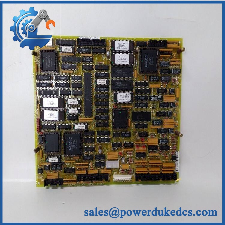
GE DS200SDCCG1AGD
G1 Group Application
GE specifically identifies the DS200SDCCG1A group for:
- AC2000 drives
- DC2000 drives
- EX2000 excitation applications
The same GE documentation distinguishes the G1 group from G3, used for DC1000 drives, and G4, used for TC2000 turbine applications.
This makes the G1 designation important when sourcing a replacement. A generic DS200SDCC board should not be treated as equivalent solely because it carries the same SDCC functional acronym.
I/O and Board Interfaces
The board uses multiple dedicated connectors to communicate with the surrounding drive hardware:
| Connector | Documented Function |
|---|---|
| 1PL | I/O between the SDCC and the power-supply/interface board |
| 2PL | ±5, ±15, and ±24 VDC power inputs |
| 3PL | SDCC outputs to the LAN Communications Card |
| 6PL | I/O with the Drive Terminal Board or Simple Drive Terminal Board |
| 7PL | I/O with the Signal Processor Card or Multibridge Signal Processing Card |
| 8PL | I/O with the Drive Terminal Board or Simple Drive Terminal Board |
| 9PL | Not used on the documented configuration |
| 11PL | SDCC outputs to meters |
The documented 11PL interface provides four configurable analog meter outputs. Each output can be assigned to a drive variable and scaled for the required meter range.
Diagnostic Features
The SDCC has a bank of 10 diagnostic LEDs. GE documents two fault-display formats:
- Faults 1–399 are displayed as BCD-coded patterns.
- Faults 400–1023 use binary-coded patterns.
- When there is no fault or the drive is not running, the LEDs perform a sequential pattern.
The LEDs can also be configured through software to provide a coarse display of drive variables while operating.
The board also has a dedicated RESET pushbutton and watchdog-based reset protection. GE cautions that a hard reset trips the system and should not normally be initiated while the equipment is running.
Configuration and Software
The SDCC uses both hardware and software configuration. Documented hardware configuration includes Berg-type jumpers and wire jumpers, with many settings established at the factory for the particular drive application. GE recommends transferring the configuration of the replaced board to the replacement board rather than assuming factory-default jumper positions are correct.
Applicable configuration tools documented by GE include ST2000, GE Control System Toolbox, and LynxOS Drive Configurator.
Important DS200 vs. DS215 Difference
This distinction is important when purchasing the board.
GE’s manual states that DS215SDCC boards contain onboard software stored in four EPROMs and one EEPROM, whereas the DS200SDCC version does not include those five memory chips; the sockets are empty.
Therefore, a supplier should not automatically describe a bare DS200SDCCG1AGD as containing the same pre-installed software/configuration hardware as a DS215SDCC.
Replacement Considerations
For replacement procurement, verify:
| Verification Item | Why It Matters |
|---|---|
| DS200SDCCG1AGD | Confirms exact board |
| G1 group | Identifies the applicable drive family |
| A functional revision | Confirms hardware revision |
| D artwork revision | Identifies PCB artwork revision |
| Host drive/exciter model | Establishes system compatibility |
| Memory-chip configuration | Critical distinction between DS200 and DS215 |
| Jumper and wire-jumper positions | Application-specific |
| Auxiliary boards | SLCC/LCC, SPC, or SPCB may be mounted on the board |
| Connector wiring | Required for correct reinstallation |
| Firmware/application parameters | Needed for correct system operation |
GE explicitly states that all digits of the catalog number are important when ordering or replacing a board. It also instructs technicians to set configurable items on the replacement SDCC to the same positions as the original board.
Lifecycle Considerations
The DS200SDCCG1AGD is legacy Mark V hardware and is generally sourced through remaining industrial automation inventory and specialist replacement channels. Current secondary-market references continue to identify the exact part number as a GE Mark V Drive Control Card.
For critical legacy equipment, the complete G1AGD identification should be retained in purchasing and asset records rather than shortening the specification to “DS200SDCC.”
Important Specification Note
Some reseller pages publish values such as 24 VDC input, 600 VDC output, 1,000 A output, or modern DSP-based control for this part. Those descriptions conflict with the GEI-100029 documentation and should not be used as confirmed specifications for the SDCC board. GE’s documentation identifies the SDCC as a control card supplied by the host drive’s power-supply/interface circuitry, with three specific 16-bit processor devices.
FAQ
It is a GE Mark V SDCC Drive Control Card, G1 group, used for AC2000, DC2000, and EX2000 drive applications.
How many processors are on the SDCC?
The documented architecture has three primary processors: 80C186 DCP, 80C196 MCP, and TMS320C25 CMP.
What does SDCC stand for?
SDCC is GE’s designation for the Drive Control Card.
What systems use the G1 version?
GE identifies the G1 SDCC group for AC2000, DC2000, and EX2000 applications.
Does the version include programmed memory chips?
GE states that the DS200SDCC does not include the five memory chips that are installed on the DS215 version.
How many diagnostic LEDs are provided?
The board has 10 diagnostic LEDs used for fault-code indication and other diagnostic displays.
The applicable GE document is GEI-100029C, SDCC Drive Control Card.
Can another DS200SDCC variant replace it?
Not automatically. GE identifies different SDCC groups for different applications, so the G1 group, revision, memory arrangement, host system, and configuration should be checked before substitution.











 Start Chat


