

Description
- Brand: GE General Electric
- Full Model Number: DS200TCEBG1ACE
- Lifecycle Status: Obsolete / discontinued
- Core Function: Mark V Common Circuits Emergency Overspeed (EOS) / Protective Termination Expander Board
- Top 3 Technical Specs: 3 bayonet connectors JWX/JWY/JWZ; 4 signal transformers; 1 × 26-pin connector
- Additional Interfaces: 4 × 10-pin connectors; 3 × 20-pin connectors
- System Family: GE Speedtronic Mark V
- Listed Weight: Approximately 0.8 kg / 1.75 lb
- Stock & Condition: New Surplus, Tested Surplus, or Tested Refurbished subject to physical stock confirmation
- Shipping: Emergency dispatch subject to confirmed inventory and carrier cutoff
The DS200TCEBG1ACE is identified in available technical references as a GE Mark V Common Circuits EOS board and Protective Termination Expander Board. The documented connector set includes three bayonet connectors labeled JWX, JWY, and JWZ, four signal transformers, one 26-pin connector, four 10-pin connectors, and three 20-pin connectors. The part is also listed as discontinued by the manufacturer in current industrial inventory records.
Obsolescence & Supply Chain Deep Dive
A failed DS200TCEBG1ACE can create a very specific maintenance problem: the installed Mark V control architecture may remain serviceable while the original spare-parts channel has already ended. Current industrial inventory references classify this part as discontinued, while other technical listings associate it with the Mark V EOS/common-circuit section. That makes the procurement objective straightforward—secure an exact, identifiable spare before an unplanned turbine outage forces a rushed search through multiple legacy-board variants. The board’s JWX, JWY, and JWZ bayonet connections and its transformer-based signal interface also make exact part identification important before ordering.
From a TCO perspective, replacing a failed board is materially different from replacing an entire turbine control system. A verified DS200TCEBG1ACE can preserve the existing Mark V cabinet, field wiring, terminal arrangement, engineering configuration, and commissioning process, avoiding the engineering and outage costs associated with a broader modernization project. For an exact same-part replacement, the technical risk is concentrated in correct installation and configuration rather than in redesigning the control architecture. That is especially relevant for aging turbine assets where capital expenditure must be justified against the remaining service life (and where emergency procurement can cost considerably more than planned spare inventory).
Compatibility & Replacement Matrix
| Buyer Review Item | DS200TCEBG1ACE Assessment |
|---|---|
| Exact-Part Replacement | Drop-in Replacement when replacing an existing DS200TCEBG1ACE |
| System Family | GE Speedtronic Mark V |
| External Connections | JWX/JWY/JWZ bayonet interfaces plus documented multi-pin connectors |
| Firmware Flash | No firmware-flash requirement identified in the hardware references reviewed |
| Hardware Modification | Normally not required for an exact same-part replacement |
| Configuration Review | Required before energization and return to service |
| Cross-Variant Replacement | Engineering verification required before substituting another DS200TCEBG1A or DS200TCEAG-series variant |
| Removal / Installation Planning | Approximately 1–3 labor hours |
| Functional Verification | Approximately 2–4 labor hours, depending on test access |
| System Upgrade Alternative | Separate Mark V migration project; not part of a board-level replacement |
Available service information places emphasis on maintaining the original installation position and correctly documenting cable connections before board removal. The connector arrangement is substantial, so cable identification should be completed before disconnecting the existing unit.
Field Traps to Watch Out For
Connector identification error: The has multiple connector families. Label every cable by connector designation before removal, then verify each connection against the original board and approved system documentation.
Variant substitution: Listings associate the with the Mark V EOS/common-circuit group, alongside other TCEB and TCEA variants. Similar family numbers do not establish interchangeability. An alternate suffix should therefore be treated as a separate engineering review item.
Signal transformer configuration: The board is documented with four signal transformers used in the signal-conditioning path. Do not assume a visually similar board has the same transformer population or wiring arrangement.
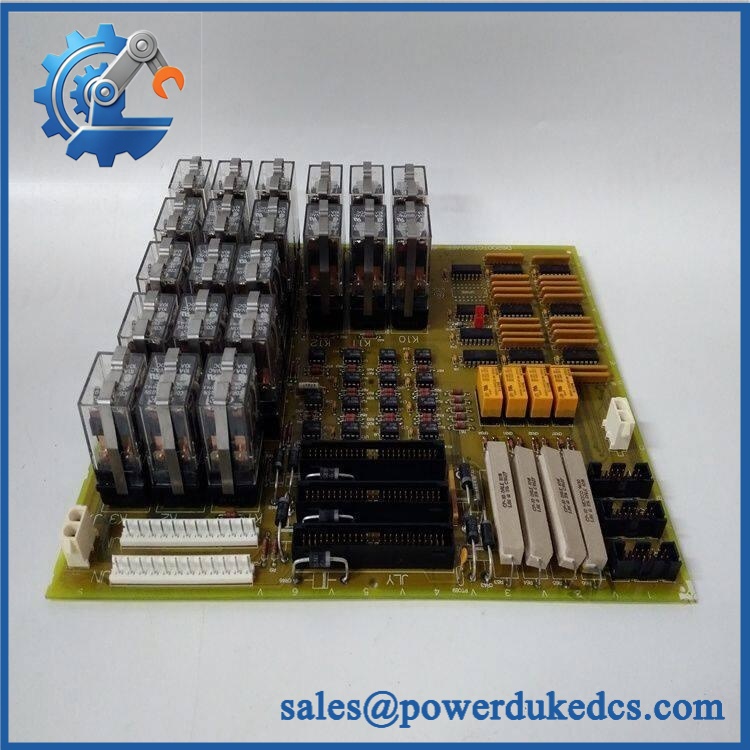
GE DS200TCEBG1ACE
Quality Assurance & Testing SOP
Part-number verification: Confirm the PCB marking against and record visible revision, serial, and manufacturing information where present. Part-number discrepancies stop the inspection.
OEM anti-counterfeit visual inspection: Compare PCB construction, component placement, connector arrangement, board markings, labels, solder workmanship, and visible manufacturing characteristics against established GE Mark V references. Suspicious relabeling, unexplained rework, or inconsistent component population triggers manual review.
Connector inspection: Inspect JWX, JWY, JWZ, the 26-pin connector, four 10-pin connectors, and three 20-pin connectors. Check for bent contacts, oxidation, cracked solder joints, contamination, physical impact, and cable-retention damage.
Transformer inspection: Visually inspect all four signal transformers for discoloration, cracked housings, damaged leads, or evidence of overheating. Where test equipment and an approved fixture are available, verify the applicable electrical characteristics against the test specification.
Power-on self-test (POST): Install the board in an approved Mark V test environment and apply controlled power. Verify power-up behavior, board status indication, and absence of abnormal electrical conditions. Test records should identify the actual diagnostic features present on the hardware rather than assuming a generic ERR/RUN LED arrangement.
I/O load testing: Connect the board to a compatible test setup and exercise representative signal paths. Verify expected signal transfer through the associated interface and check for intermittent behavior, unstable values, or abnormal response.
Cable and connection verification: Confirm that every tested connector corresponds to the intended interface and that no pin or cable position has been altered during test setup.
Final QA release: Record exact part number, revision, serial number when available, visual inspection result, connector condition, power-up result, signal-test result, technician identification, and inspection date. Accepted units are packed using ESD protection and mechanical cushioning suitable for international shipment.
Procurement & Lifecycle FAQ
Is the genuinely in stock and what is the cutoff for emergency shipping?
Physical stock should be confirmed against the actual unit before the PO is released. Current inventory listings show units offered in unused and refurbished conditions, while availability varies by supplier and stock location. For an emergency requirement, confirm quantity, exact suffix, physical condition, destination, and carrier cutoff before payment.
How do you guarantee the condition and authenticity of an obsolete ?
The purchase record should clearly state whether the supplied unit is New Surplus, Tested Surplus, or Tested Refurbished. A suitable QA record includes exact part-number verification, label and PCB inspection, connector inspection, configuration documentation, controlled power-up, and functional signal testing. Do not treat a catalog photograph or a family-level description as proof of the condition of the physical unit.
Are there any firmware compatibility issues engineers should review before issuing the PO?
No firmware-flash requirement was identified in the hardware references reviewed. The larger concern is hardware and connection compatibility, particularly the multiple JWX/JWY/JWZ bayonet connections and associated multi-pin connectors. Engineers should verify the exact part number, revision, installation position, and cable arrangement.
Is the a direct replacement for an installed board?
For an existing , an exact same-part replacement can generally be treated as a board-level drop-in replacement. Replacing it with another TCEB/TCEA variant requires a separate compatibility check because family-level similarity does not by itself establish electrical or application interchangeability.
What warranty and return terms should procurement require?
The PO should specify the exact model, revision where applicable, condition category, test status, warranty duration, DOA definition, return window, and return-freight responsibility. This is particularly important for discontinued inventory because available units may be sold under different condition classifications and warranty arrangements. Current industrial listings, for example, show different warranty structures depending on the supplier and condition offered.











 Start Chat


