

Description
- Brand: GE General Electric
- Full Model Number: DS3800DFXA1B1C
- Lifecycle Status: Legacy / Obsolete
- Core Function: Mark V TCQA analog I/O board for signal scaling, conditioning, and processing
- Top 3 Technical Specs: Mark V LM platform; six 34-pin connectors; hardware jumpers J1, J2, J5, J6, J7, J8
- Supported Signal Types: LVDT; 4–20 mA; thermocouple; pulse-rate; vibration; voltage; servo-related signals
- Primary Core Connections: 2PL power distribution; 3PL data bus; JA/JB/JD/JE/JG signal interfaces
- mA Output Configuration: J1/J2 selection; J5/J6 range configuration
- Test Interface: RS-232 connection at J7
- Stock & Condition: New Surplus, Tested Surplus, or Tested Refurbished subject to physical-unit confirmation
- Shipping: Emergency dispatch subject to confirmed inventory and carrier cutoff
The DS3800DFXA1B1C is identified in available technical references as a GE Mark V LM analog I/O board, commonly described as a TCQA board. Its documented role is to scale and condition multiple turbine-control signals, including LVDT, 4–20 mA, thermocouple, pulse-rate, vibration, and voltage-related inputs or outputs. The board documentation also identifies six 34-pin connectors and a set of hardware jumpers used for configuration and testing.
Obsolescence & Supply Chain Deep Dive
A failed DS3800DFXA1B1C can leave an otherwise serviceable Mark V installation with a very specific spare-parts problem: the controller remains in production service, but the original board is no longer part of a normal new-equipment supply chain. Available references classify the board as legacy/obsolete and associate it with the Mark V LM turbine-control architecture. The board handles signal scaling and conditioning across several important turbine I/O paths, so an exact identified spare can be more practical than waiting for a repair cycle or approving a broader controls project. For procurement, the full DS3800DFXA1B1C designation matters; visually similar Mark V analog boards should not be accepted as automatic substitutes.
The TCO case centers on preserving an existing installed system. A board-level replacement can retain the existing I/O core, terminal-board wiring, application configuration, engineering documentation, and commissioning procedures rather than triggering a full controls migration. That can reduce engineering labor and outage exposure substantially when the installed Mark V remains serviceable (though revision-specific configuration must still be checked before installation). The documented TCQA hardware configuration includes jumpers for mA output selection and range, plus an RS-232 test connection, so the replacement process should include configuration verification rather than treating the transaction as a simple visual swap.
Compatibility & Replacement Matrix
| Buyer Review Item | DS3800DFXA1B1C Assessment |
|---|---|
| Exact-Part Replacement | Drop-in Replacement for an existing DS3800DFXA1B1C application, subject to revision and configuration verification |
| System Family | GE Mark V LM turbine control system |
| Board Function | TCQA analog I/O signal scaling and conditioning |
| Connector Architecture | Six documented 34-pin interfaces including 2PL, 3PL, JA, JB, JD, JE, and JG signal-routing references across the board documentation |
| Firmware Flash | No routine firmware-flash requirement identified in the technical references reviewed |
| Hardware Modification | Normally not required for an exact same-part replacement |
| Configuration Work | Required — verify jumper positions, connector assignments, and application settings |
| mA Output Settings | J1/J2 used for output-circuit selection; J5/J6 used for output-current range configuration |
| Test Interface | RS-232 connection identified at J7 |
| Installation Labor | Planning allowance: approximately 1–3 hours |
| Functional Verification | Planning allowance: approximately 2–4 hours, depending on site access and test equipment |
| Cross-Variant Replacement | Engineering validation required before substituting another TCQA/Mark V board |
Field Traps to Watch Out For
Connector mapping error: The board uses multiple 34-pin connectors with different functions. The technical reference identifies 2PL as a power-distribution connection, 3PL as the core data-bus path, and JA/JB/JD/JE/JG for specific signal-routing functions. Label every ribbon cable before removal and reproduce the original connection map during installation.
mA output-range configuration: J1/J2 are used to select the mA output circuit, while J5/J6 configure the output-current range, including documented 20 mA and 200 mA maximum settings. An incorrect jumper state can produce an apparently healthy board with an incorrect field signal range. Verify the installed configuration against the original board and the approved application documentation.
Core-specific application differences: The board is described in references as serving I/O cores R1, R2, and R3, but individual connector functions can vary by core position. Do not approve a substitution based only on the common TCQA designation.
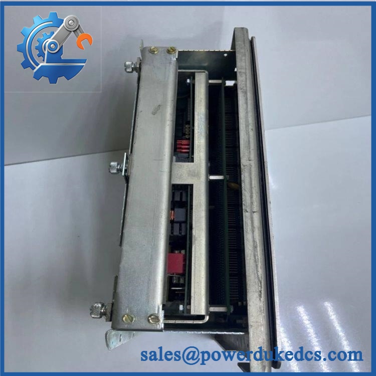
GE DS3800DFXA1B1C
Quality Assurance & Testing SOP
Part-number verification: Confirm the PCB marking as and record all visible revision, serial, and manufacturing identifiers. Any discrepancy between the purchase specification and physical board stops the inspection.
OEM anti-counterfeit visual inspection: Examine board construction, component population, labels, connector numbering, PCB markings, solder workmanship, and visible manufacturing characteristics against established GE Mark V references. Relabeled boards, unexplained rework, inconsistent component populations, or damaged markings require manual review.
Connector inspection: Inspect the six 34-pin interfaces and all accessible connector hardware for bent contacts, oxidation, contamination, cracked solder joints, PCB lifting, mechanical impact, or signs of cable stress. Connector condition is documented before electrical testing.
Jumper configuration capture: Photograph and record J1, J2, J5, J6, J7, and J8 before any configuration changes. Confirm the existing configuration against the customer’s original board where available.
Power-on self-test (POST): Install the in an approved Mark V test environment and apply controlled power. Verify expected board startup behavior and monitor available status indications throughout initialization.
Analog signal simulation: Apply controlled representative signals through the approved test fixture, including applicable 4–20 mA, thermocouple, LVDT, pulse-rate, or voltage channels supported by the test setup. Check scaling, signal stability, and response against the defined test limits.
I/O load testing: Exercise representative analog output paths under controlled loads. Verify the selected output range corresponds to the configured jumper state, with particular attention to the J1/J2 and J5/J6 configuration.
RS-232 test verification: Where the available test fixture supports it, verify the documented J7 RS-232 test interface and confirm stable communication during controlled diagnostics.
Final QA release: Record the exact part number, revision, serial number where available, connector inspection, jumper photographs, POST result, analog I/O test results, technician identification, and test date. Accepted boards are packaged in ESD-protective material with mechanical cushioning for shipment.
Procurement & Lifecycle FAQ
Is the genuinely in stock and what is the cutoff for emergency shipping?
Current industrial listings show inventory in unused and rebuilt/refurbished conditions, including listings advertising same-day shipment. Real-time quantity still needs to be confirmed against the physical stock position before the PO is released. For emergency requirements, confirm quantity, exact suffix, condition, destination, and carrier cutoff before payment.
How do you verify the condition and authenticity of an obsolete ?
The inspection should cover exact part-number verification, PCB and connector examination, visible component review, jumper/configuration documentation, controlled power-up, and representative analog I/O testing. Commercially, the unit should be identified precisely as New Surplus, Tested Surplus, or Tested Refurbished rather than using one generic condition label.
Are there firmware compatibility issues engineers should review before issuing the PO?
No routine firmware-flash requirement was identified in the technical references reviewed. The more important compatibility checks concern hardware revision, connector assignment, jumper configuration, and the installed Mark V I/O-core application. The documented board configuration includes J1/J2, J5/J6, J7, and J8 functions that should be matched to the installed setup before energization.
Is the a direct replacement for an installed board?
For an existing , an exact same-part unit can generally be handled as a board-level replacement without planned hardware modification. A different DS3800DFX or TCQA variant should be treated as a separate engineering approval because connector functions, configuration, and application assignment may differ.
What warranty and return terms should procurement require?
The PO should specify the exact model, revision where applicable, condition classification, inspection status, warranty duration, DOA definition, return window, and return-freight responsibility. For legacy boards, these commercial terms should be agreed in writing before shipment because New Surplus, Tested Surplus, and Refurbished units can carry different warranty conditions.











 Start Chat


