

Description
- Brand: GE Multilin / GE Vernova
- Full Model Number: G60E00HAHF8LHXXM8LPXXUXXWXX
- Lifecycle Status: Active G60 product family; exact configured order code requires stock verification
- Core Function: Generator protection, control, metering, monitoring, and disturbance recording
- Top 3 Technical Specs: 1 A CT input configuration; F8L standard 4CT/4VT module; 125/250 V AC/DC power supply configuration
- Protection Functions: Stator differential; ground fault; loss of excitation; over/under voltage; over/under frequency; phase and ground overcurrent; breaker failure
- Communications: RS-485 base communications; network options are configuration dependent
- CT/VT Hardware: F8L; standard 4CT/4VT with enhanced diagnostics
- Software Environment: EnerVista UR Setup / applicable G60 firmware
- Stock & Condition: New surplus / tested replacement; exact firmware, settings, and hardware condition to be confirmed
- Emergency Shipping: Subject to physical-stock confirmation and carrier cutoff
GE’s G60 is a modular generator protection system for medium and large generators. The manufacturer’s ordering documentation identifies F8L as the standard 4CT/4VT module with enhanced diagnostics and H power-supply selection as 125/250 V AC/DC.
For the exact order string supplied here, a current specialist listing identifies the configuration as G60E00HAHF8LHXXM8LPXXUXXWXX and associates it with a 1 A CT input, high-impedance differential protection, and universal control-power capability. Because those details come from a secondary listing rather than the current GE order-code table, the relay nameplate and configuration file should control the final purchasing decision.
Obsolescence & Supply Chain Deep Dive
A generator protection relay failure can turn into an outage-management problem before the replacement quotation is even approved. The G60E00HAHF8LHXXM8LPXXUXXWXX is a configuration-specific G60 assembly, not a generic relay with interchangeable electronics. Its CT/VT arrangement, communication hardware, I/O population, power supply, front panel, firmware, and protection settings all contribute to the actual installed configuration. GE continues to document and support the G60 product family, while the exact long-form configuration string is typically sourced as a configured or replacement unit.
The TCO calculation changes significantly when the generator, switchgear, wiring, and protection scheme remain serviceable. Replacing the relay with an appropriately matched unit can avoid panel redesign, revised CT/VT wiring, protection-setting redevelopment, communications engineering, and a larger modernization project. GE’s G60 platform provides generator stator differential, ground-fault, loss-of-excitation, overexcitation, negative-sequence, reverse-power, breaker-failure, voltage, frequency, and related protection functions within the same relay family. A tested surplus unit can shorten procurement time when exact legacy-configured stock is available, although actual lead time depends on firmware, configuration review, inspection, and shipment requirements.
Compatibility & Replacement Matrix
| Procurement / Engineering Item | Assessment |
|---|---|
| Replacement Classification | Conditional Drop-in Replacement |
| Best Match | Exact G60 order code with matching hardware and firmware |
| Primary Application | Medium and large generator protection |
| CT/VT Configuration | F8L; standard 4CT/4VT with enhanced diagnostics |
| Specified CT Input | 1 A for the exact configuration reported by the secondary supplier |
| Power Supply | 125/250 V AC/DC configuration indicated by the H power-supply code |
| Firmware Flash Required | Not automatically required; verify installed firmware before commissioning |
| Settings Transfer | Required unless the replacement is supplied with the approved site configuration |
| Hardware Modification | Normally none for an exact configuration match |
| Typical Relay Exchange Time | Approximately 3–6 labor hours, excluding testing and fault investigation |
| Budgetary Field Labor | Approximately USD 500–1,500 depending on site rates and commissioning scope |
| Commissioning | Mandatory secondary-injection, logic, trip, communications, and settings verification |
Field Traps
CT rating mismatch:
The exact configuration is reported with 1 A CT inputs. A 5 A CT circuit must not be connected directly merely because the relay family is also available with 5 A configurations. Confirm the CT module identification and every connected CT secondary before energization.
CPU and CT/VT module mismatch:
GE’s G60 documentation warns that newer CT/VT modules are compatible only with the corresponding newer CPU generation, while older CT/VT modules require the appropriate older CPU. A mismatch can prevent normal relay operation and generate a hardware-mismatch error. This is a particularly important inspection point on replacement units.
Order-code drift:
Two G60 relays can share the same chassis while having different CT/VT modules, digital I/O, transducer I/O, communication ports, software options, or front panels. Match the full ordering string, not just “G60.” GE’s configuration matrix explicitly treats these options as separate hardware or software selections.
Settings are not interchangeable by default:
Even with matching hardware, the replacement relay must carry the correct site settings, FlexLogic, CT/VT ratios, protection pickup values, communication parameters, and trip logic. A hardware match is not proof of a commissioning-ready relay.
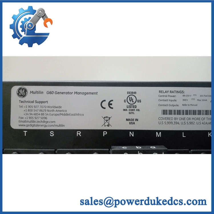
GE G60E00HAHF8LHXXM8LPXXUXXWXX
Quality Assurance & Testing SOP
The pre-shipment procedure for a configured G60 should resemble a protection-relay laboratory acceptance test, not a simple visual inspection.
OEM anti-counterfeit visual inspection
Verify GE identification, complete order code, serial information where available, front-panel assembly, module labels, terminal blocks, chassis condition, PCB construction, connector geometry, and visible manufacturing details. Capture photographs of the relay nameplate and module arrangement.
Configuration verification
Record the complete G60E00HAHF8LHXXM8LPXXUXXWXX string exactly as supplied. Compare the actual relay configuration against the buyer’s existing order code, drawings, and approved bill of materials.
CT/VT module verification
Confirm the installed CT/VT module corresponds to the expected F8L configuration. GE documentation identifies 8L as standard 4CT/4VT with enhanced diagnostics. Do not substitute another CT/VT module based solely on connector compatibility.
Power-on self-test
Energize the relay using the specified control-power arrangement and run the G60 self-test sequence. Check the front-panel status indicators, display, target/alarm indications, and diagnostic messages. GE’s documentation provides dedicated self-test reporting and testing functions through the relay interface.
ERR/RUN status verification
Record the actual front-panel operating and fault indications during startup. Because G60 front-panel layouts vary with the ordered interface option, the tester should document the indicators present on the specific unit rather than assuming a universal LED arrangement.
Secondary injection testing
Use a calibrated protection-relay test set to inject representative current and voltage signals. Verify measurement accuracy, phase relationships, protection pickup, timing, restraint behavior, and relevant trip logic according to the approved site test plan.
I/O load testing
Exercise representative contact inputs and outputs under controlled conditions. Confirm digital-input recognition, output operation, trip-contact behavior, and return-to-normal states. G60 documentation provides test facilities for contact inputs and outputs as well as selected communication functions.
Protection-function verification
Where required by the application, test representative functions such as 50/51, 50G/51G, 27/59, 81O/81U, 40, 46, 50BF, 87S, 87RGF, and related programmed elements. The exact test list must follow the customer’s approved protection scheme rather than assuming every G60 feature is enabled.
Communication testing
Verify the installed communications interfaces and expected protocol operation. G60 configurations can include RS-485, Ethernet, IEC 61850, EGD, process-bus, and inter-relay communication options depending on the order code.
Firmware and settings record
Record the exact firmware revision, settings-file identifier, active setting group, communication parameters, and software-option status. GE documentation shows that firmware revision is part of the relay’s generated fault and configuration information.
Final QC release
Maintain the nameplate photographs, order-code record, firmware report, test-set results, I/O results, protection test report, inspection checklist, and packing photographs. Test videos can be retained for critical-spare approval.
Procurement & Lifecycle FAQ
Is GE G60E00HAHF8LHXXM8LPXXUXXWXX available for emergency shipment?
Current specialist listings show this exact order code in inventory, including listings identifying a corresponding internal stock reference. That is a supplier-specific stock position, so emergency buyers should confirm physical availability, exact hardware configuration, firmware revision, condition, and carrier cutoff on the day the PO is released.
How do you verify authenticity and condition for a configured G60 relay?
Require the complete order code, serial or identification information where available, photographs of the front and rear assemblies, CT/VT module identification, firmware revision, and functional test documentation. For a critical generator relay, request evidence of secondary-injection testing and I/O verification rather than accepting a power-on statement alone.
Are there firmware compatibility issues before issuing the PO?
Yes. The G60 is a firmware-dependent protection platform, and the firmware revision can affect available functions and compatibility with specific hardware generations. GE documentation also warns about CPU and CT/VT module generation mismatches. Before approving the purchase, compare the installed relay’s firmware, CPU generation, CT/VT module, software options, and settings file against the replacement.
Is this an exact drop-in replacement for another G60 relay?
Only when the replacement matches the required hardware configuration and the commissioning data. The F8L CT/VT configuration, power supply, communications, I/O options, firmware, and protection settings all need verification. GE’s ordering documentation shows that G60 configurations can differ substantially even within the same relay family.
What warranty and return terms should be written into the PO?
Specify the complete order code, hardware configuration, firmware revision, condition, test scope, warranty duration, DOA definition, return authorization process, and approved-return freight responsibility. For a protection relay, the acceptance criteria should also define whether incorrect settings, configuration mismatch, or confirmed hardware failure qualifies for return.











 Start Chat


