

Description
- Brand: GE Fanuc
- Full Model Number: IC670CHS002
- System/Series Family: GE Field Control Distributed I/O
- One-Sentence Core Function: Box-terminal I/O base providing module mounting, backplane communication, field wiring, and common/power terminals for Field Control I/O modules
- Top 3 Hardcore Specs: 51 terminals; supports 2 I/O modules; AWG 14–22 field wiring
- Terminal Type: Box terminals
- Maximum Terminal Current: 10 A
- Mounting: Field Control I/O station terminal-base architecture
- Stock Status: New Surplus / Fully Tested Refurbished subject to actual inventory inspection
Module 3: Commercial-Technical Deep Dive
A Field Control I/O station can become difficult to troubleshoot when the electronics are healthy but the terminal base has a damaged connection, loose terminal, or failed backplane interface. The GE IC670CHS002 is the Field Control I/O Terminal Block with Box Terminals, providing the mounting, backplane communications, field-wiring terminals, and common/power connections for Field Control modules. GE documentation specifies 51 terminals on the IC670CHS002, and the mechanical design permits two I/O modules to be installed on one terminal block. Modules screw onto the terminal block, while field wiring can remain in place during module removal.
The practical advantage is serviceability rather than processing performance. Each terminal accommodates either one AWG #14 to AWG #22 conductor or two conductors up to AWG #18, while the published specification gives a 10 A maximum current per terminal. The terminal base also provides three isolated groups of common terminals: A and B groups for power connections and the E group for application wiring. Terminals 1–16 provide the principal I/O connections for each module position. That architecture makes exact terminal mapping important during replacement. A visually identical Field Control base with a different terminal style—such as barrier terminals or wire-to-board connectors—is not a wiring-equivalent substitute.
Module 4: Compatibility & Installation Traps
Migration/Compatibility
- Replacement status: GE Fanuc Field Control I/O Terminal Block with Box Terminals
- Logic rewrite: Not required. The IC670CHS002 is a terminal-base/interconnection component rather than a programmable controller.
- Firmware flash: Not applicable.
- Drop-in status: Direct replacement is generally practical when the existing Field Control station uses the same IC670CHS002 terminal style and compatible I/O modules.
- Terminal count: 51 terminals.
- Module capacity: Two I/O modules per terminal block.
- Terminal type: Box terminals, not barrier terminals or plug-in I/O connectors.
- Wire range: One AWG #14–#22 wire, or two wires up to AWG #18.
- Maximum terminal current: 10 A.
- Related versions: IC670CHS102 is the later box-terminal version; GE documentation distinguishes it from the IC670CHS002 generation.
⚠️ Field Traps (Watch Out)
- Terminal-style mismatch: GE Field Control uses three different terminal styles: box terminals, barrier terminals, and wire-to-board connectors. is specifically the box-terminal version.
- Two-module layout: One accepts two I/O modules. Record which module occupies each position before removing the original base.
- Common-terminal grouping: A1/A2 are internally common, B1/B2 are internally common, and E1/E2/E4/E6/E8 are internally connected. Do not repurpose these terminals without checking the applicable wiring diagram.
- Terminal current limit: The 10 A terminal rating is not an I/O-module rating. The connected Field Control module may impose a substantially lower current limit.
- Wire termination: GE specifies a recommended terminal torque of 4.5 in-lb and 90 °C copper conductors in the applicable terminal-base documentation.
- Mixed-base installations: GE documentation advises against mixing the later IC670CHS10x terminal blocks with IC670CHS00x terminal blocks in the same I/O station.
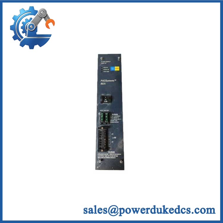
GE IC670CHS002
Module 5: Quality Assurance SOP
Before shipment, the should undergo a terminal-base-specific inspection:
- OEM anti-counterfeit visual inspection — verify GE Fanuc markings, catalog number, box-terminal geometry, molded housing, terminal numbering, and identification labels.
- Mechanical inspection — inspect the mounting structure, module retention screws, terminal housing, terminal barriers, connector interfaces, and plastic components for cracks or deformation.
- Terminal inspection — inspect all 51 terminals for damaged threads, loose hardware, corrosion, contamination, or recessed contacts.
- Wire-retention verification — test representative terminals with approved conductor sizes and confirm reliable mechanical retention.
- Continuity verification — check representative field-terminal-to-module-interface paths against the applicable GE wiring documentation.
- Common-terminal verification — confirm the internal commoning of A1/A2, B1/B2, and the E-terminal group using controlled continuity measurements.
- Module-interface test — install compatible Field Control I/O modules in both positions and verify proper mechanical seating and electrical engagement.
- Backplane communication handshake — connect the terminal base to a compatible Field Control Bus Interface Unit and verify module recognition and data exchange.
- Field-signal continuity test — inject controlled signals through representative terminals and confirm correct transmission to the installed I/O modules.
- Mechanical retention test — verify module screw retention and terminal-base mounting stability.
- Final QC record — document exact part number, terminal condition, test modules, continuity results, station configuration, photographs, and packaging condition.
For a Field Control terminal base, cosmetic inspection is not enough. Terminal integrity, internal commoning, module engagement, backplane continuity, and successful I/O communication are the meaningful acceptance checks.
Module 6: CRO-Driven Buyer FAQ
1. Is GE obsolete, and how do I verify an authentic replacement?
The is legacy GE Fanuc Field Control hardware, documented as an I/O Terminal Block with Box Terminals. GE documentation distinguishes it from the IC670CHS001 barrier-terminal base and IC670CHS003 connector-based terminal block. For procurement, verify the exact marking and box-terminal layout rather than ordering a generic Field Control base.
2. Can I hot-swap the ?
Do not assume that the terminal base itself can be removed while energized. GE documents hot insertion/removal for certain later Field Control terminal-block/module combinations, but the documented permission is version- and environment-dependent; hazardous locations require I/O-station power to be turned off. Use the applicable GE installation procedure and site LOTO requirements.
3. Will replacing require PLC programming?
No. The terminal block is a passive field-wiring and backplane component. After replacement, verify terminal mapping, common connections, module seating, Field Control Bus communication, and I/O operation.
4. How many terminals and modules does support?
The provides 51 terminals and allows two I/O modules to be installed on one terminal block. Each terminal accepts one AWG #14–#22 conductor or two conductors up to AWG #18, with a maximum stated terminal current of 10 A.
5. What is the difference between and IC670CHS001?
uses box terminals and has 51 terminals, while IC670CHS001 uses barrier terminals and has 37 terminals. They are different field-wiring interfaces and should not be substituted without checking the complete station wiring and module configuration.
Warranty and Technical Support
Warranty duration should be stated according to the actual inventory condition, such as new surplus or tested refurbished. Technical support should cover exact terminal-base identification, module compatibility, terminal mapping, common-terminal verification, Field Control Bus testing, and documented pre-shipment inspection. Live field rewiring and energized maintenance remain the responsibility of qualified automation personnel.











 Start Chat


