

Description
- Brand: GE / General Electric
- Full Model Number: IS200AEPAH1BJD
- Associated Identifier: JE200Z7 — buyer-supplied identifier; OEM mapping should be verified
- Lifecycle Status: Legacy / Obsolete spare; exact OEM EOL date not publicly confirmed
- Core Function: Wind Energy Pitch Axis control PCB for GE Mark VIe wind turbine systems
- Top 3 Technical Specs: 125 VDC supply rating; 8 analog inputs plus 1 incremental encoder input; 20 discrete inputs
- Additional I/O: 1 dedicated analog input; 2 discrete outputs; 9 relay outputs; 2 PWM control outputs
- Communications: 2 RS-485 interfaces; Ethernet interface; 3 listed communication connectors
- Functional Acronym: WEPA
- Related Assembly Reference: IS215WEPAH2BB
- Manual Reference: GEP-9145
- Software Frame Rates: 10 ms / 20 ms / 40 ms
- Stock & Condition: New Original, New Surplus, or tested inventory subject to unit-level confirmation
- Shipping: Emergency dispatch subject to physical stock verification and carrier cutoff
Multiple technical references identify the IS200AEPAH1BJD as a WEPA wind-energy pitch-axis PCB and associate it with the IS215WEPAH2BB assembly used in GE wind control applications. Published specifications describe 125 VDC operation, multiple analog and discrete I/O channels, encoder feedback, RS-485 interfaces, and PWM outputs.
Obsolescence & Supply Chain Deep Dive
A failed pitch-axis control board can stop a wind turbine even when the mechanical pitch system remains serviceable. The procurement challenge is more than finding an electrically similar PCB: the replacement has to match the existing WEPA hardware revision, I/O architecture, application configuration, and turbine control environment. The IS200AEPAH1BJD is identified in current industrial documentation as a Wind Energy Pitch Axis board, commonly cross-referenced with IS215WEPAH2BB and manual GEP-9145. The board is associated with Mark VIe wind control applications and can be used in configurations supporting simplex or redundant control architectures. For plants maintaining an installed GE wind fleet, securing an exact replacement can avoid a much broader redesign involving pitch-controller conversion, application validation, cabinet changes, and turbine recommissioning. —Lead time for a factory-new legacy assembly can vary significantly, so verified physical inventory is more meaningful than a catalog-only availability statement.
The TCO advantage comes from preserving existing engineering investment. The documented WEPA architecture provides analog inputs, incremental encoder feedback, discrete I/O, relay outputs, RS-485 communication, and PWM control channels within a single pitch-axis control assembly. Published documentation also identifies 10, 20, and 40 ms software frame-rate options. Replacing a failed board with the same approved assembly can therefore keep existing wiring, control logic, maintenance procedures, and commissioning records in service rather than forcing an immediate control-system migration. As a planning estimate, allow approximately 2-4 hours for identification, board replacement, communications checks, and functional verification when the replacement configuration is already known. A broader migration should be budgeted separately because engineering validation and turbine commissioning can dominate the total replacement cost.
Compatibility & Replacement Matrix
| Replacement Scenario | Assessment | Engineering / Procurement Action | Planning Allowance |
|---|---|---|---|
| IS200AEPAH1BJD → IS200AEPAH1BJD | Drop-in Replacement when the replacement carries the same full ordering code and approved hardware revision | Match nameplate, revision, connector arrangement, application configuration, and cabinet position before installation | Approx. 2-4 hours |
| IS200AEPAH1BJD → IS215WEPAH2BB | Software / Hardware Assembly Compatibility Requires Verification | These identifiers are associated in published references, but do not treat them as interchangeable without confirming the actual GE application and BOM | Approx. 4-8 hours plus validation |
| Different WEPA revision → existing control application | Software Compatibility Requires Review | Compare application version, frame-rate configuration, I/O allocation, and turbine-specific parameters | Approx. 4-8 hours |
| Different board family → WEPA installation | Hardware Modification Required | Review connectors, signal interfaces, communications, power, and cabinet mounting before any substitution | Several engineering days |
| Exact spare with matching configuration | Preferred like-for-like maintenance path | Preserve existing application data and document pre/post-change settings | Site-dependent |
Field Traps — Watch Out
Related-Part Number Confusion: Published sources associate IS200AEPAH1BJD with IS215WEPAH2BB, but other WEPA references also exist, including IS215WEPAH2BA, IS215WEPAH2BC, and other board revisions. A suffix change should never be approved solely because the functional acronym is the same.
Application and Frame-Rate Mismatch: WEPA documentation describes 10 ms, 20 ms, and 40 ms software frame rates. The replacement must be checked against the installed turbine application rather than assumed to use a default configuration.
I/O Mapping Risk: The documented board architecture includes analog, encoder, discrete, relay, RS-485, and PWM interfaces. Verify every field channel against the existing application configuration before removing the failed board, especially where the pitch controller is tied into safety or emergency-stop logic.
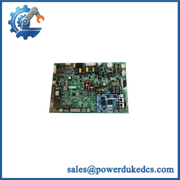
GE IS200AEPAH1BJD
Quality Assurance & Testing SOP
This board should be treated as a turbine control asset requiring unit-level verification. A visual inspection alone is not sufficient for a procurement release.
- OEM anti-counterfeit visual inspection: Compare GE markings, board designation, functional acronym, connector layout, revision identification, PCB construction, daughterboard arrangement, protective coating, and component placement against documented reference material.
- Part-number verification: Record the complete identifier and any associated IS215WEPAH2BB marking where present. Capture serial and revision information when available.
- Power-on bench test: Energize the board under the specified 125 VDC environment using a controlled test fixture and monitor startup behavior, current draw, processor initialization, and fault indications.
- Host-system POST verification: Where a compatible Mark VIe test environment is available, verify controller recognition, initialization, communications status, and expected diagnostic behavior. Do not apply conventional PLC RUN/ERR assumptions to this PCB.
- I/O load testing: Exercise representative analog, discrete, relay, and PWM channels with controlled loads appropriate to the interface ratings and intended test fixture.
- Encoder simulation: Inject representative incremental encoder signals and confirm that feedback is detected and processed correctly.
- RS-485 communication test: Verify both documented RS-485 interfaces with the appropriate test configuration and check for stable communication without intermittent framing or timeout behavior.
- Ethernet interface check: Confirm physical link and expected communication behavior where the available bench configuration supports the installed protocol stack.
- Configuration validation: Compare application parameters, I/O allocation, software frame rate, and revision information before shipment.
- Extended observation: Run repeated control and communications cycles to screen for intermittent resets, communication loss, abnormal heating, unstable outputs, or startup faults.
Published technical references describe the board with 125 VDC power, 10/20/40 ms software frame rates, 2 RS-485 interfaces, 8 analog inputs plus an incremental encoder input, 20 discrete inputs, 9 relay outputs, 2 discrete outputs, and 2 PWM control outputs.
Procurement & Lifecycle FAQ
Is the genuinely in stock, and what is the cutoff for emergency shipping?
Availability should be confirmed against physical inventory before the PO is released. Current industrial listings show active secondary-market availability for the and associated IS215WEPAH2BB assembly, but these listings do not establish OEM production availability. For emergency orders, the actual dispatch cutoff depends on physical stock confirmation, payment clearance, destination, and carrier acceptance.
How do you verify the condition and authenticity of an obsolete or legacy ?
The procurement file should contain the exact part number, visible GE identification, serial or revision data where available, actual-unit photographs on request, inspection records, power-up test results, communications checks, I/O test results, and the agreed warranty terms. For a legacy turbine board, this unit-level evidence provides a clearer audit trail than a generic product description.
Are there firmware or configuration issues engineers should check before issuing the PO?
Yes. Review the WEPA hardware revision, application version, I/O assignments, software frame rate, encoder configuration, communications parameters, and turbine-specific control settings. The documented 10/20/40 ms frame-rate options are particularly important when matching a replacement to an existing control application.
Can be purchased as a replacement for ?
The two identifiers are associated in multiple industrial references, but that does not make every unit an unconditional direct substitute. Published documentation treats the WEPA assembly as an application-specific control component, so the actual turbine configuration, revision, connector set, software, and I/O allocation must be verified before approval.
What are the warranty and return terms?
The applicable warranty period, DOA coverage, inspection window, and RMA conditions should be written into the quotation and PI for the specific unit supplied. The purchasing record should retain the quoted model, condition, serial or revision information, test documentation, and agreed return conditions.











 Start Chat


