

Description
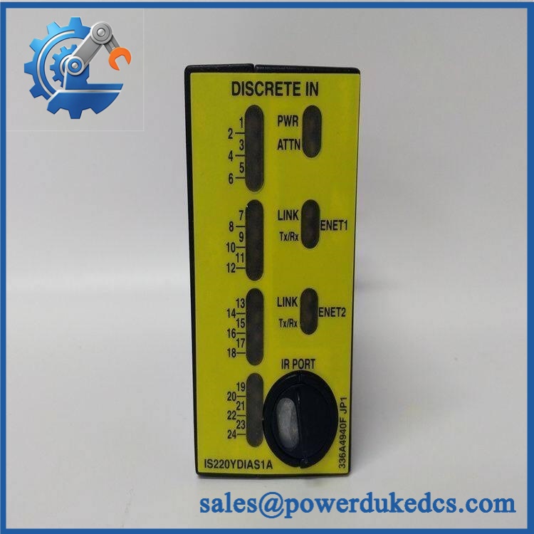
- Model: GE IS220YDIAS1A
- Brand: General Electric
- Series: Mark VIeS Safety Control System
- Part Type: YDIA Safety Discrete Contact Input I/O Pack
- Core Function: Acquires 24 discrete/contact input signals and transfers their validated status into the Mark VIeS safety-control architecture.
- Key Specs: 24 input channels, optical isolation, approximately 1500 V isolation strength, 4 ms hardware input filtering, 28 VDC nominal I/O-pack supply, and support for multiple compatible contact-input terminal boards.
- Safety Architecture: Designed for Mark VIeS safety applications; exact safety performance depends on the complete certified hardware, firmware, terminal-board, and system configuration.
Product Introduction
A turbine trip circuit can remain electrically intact while the control system loses reliable knowledge of a field contact state. The GE IS220YDIAS1A addresses that interface problem as a Mark VIeS 24-channel discrete contact-input I/O pack, using isolated input circuitry and onboard diagnostics to acquire field contact information. In field deployments, that makes correct terminal-board selection just as important as the I/O-pack part number itself.
The YDIA uses a BPPB processor board and a dedicated discrete-input acquisition board, with hardware revisions documented for the Mark VIeS safety platform. Its supported terminal-board family includes IS200STCIS1A, IS200STCIS2A, IS400STCIS1A, IS400STCIS2A, and IS200TBCIS2C. The module is now a legacy-migration item, so maintaining verified New Original or fully tested surplus stock can be important where the existing safety system has not yet been migrated.
Core Technical Specifications
| Parameter | Value |
|---|---|
| Manufacturer | GE General Electric |
| Model | IS220YDIAS1A |
| Series | Mark VIeS |
| Functional Acronym | YDIA |
| Product Type | Safety Discrete Contact Input I/O Pack |
| Input Channels | 24 discrete/contact inputs |
| Input Type | Voltage/contact input |
| Isolation | Optical isolation |
| Isolation Strength | Approximately 1500 V |
| Input Filter | Hardware filter, approximately 4 ms time constant |
| AC Rejection | Approximately 60 V RMS at 50/60 Hz under specified input conditions |
| Event Sequence Capability | Up to 1000 Hz for applicable sequence-of-events processing |
| Nominal I/O Pack Supply | 28.0 VDC |
| Maximum I/O Pack Current | 0.23 A |
| Approximate Electrical Load | About 6.4 W at maximum rated current |
| Processor Board | IS200BPPBS2B / IS200BPPBS2C hardware families documented for YDIA |
| Acquisition Board | IS200BPDIS1A |
| Compatible Terminal Boards | IS200STCIS1A, IS200STCIS2A, IS400STCIS1A, IS400STCIS2A, IS200TBCIS2C, IS400TBCIS2C |
| Terminal-Board Input Classes | Configuration-dependent, including 24 VDC, 48 VDC, and 125 VDC variants |
| Communication | Mark VIeS I/O Ethernet architecture |
| Diagnostic Functions | Power-on self-test, periodic functional testing, input-response monitoring, terminal-board mismatch detection |
| Operating Temperature | Approximately -30°C to +65°C |
| Physical Dimensions | Approximately 82.6 H × 41.9 W × 121 D mm |
| Firmware | Safety-system dependent |
| Hot Swap | Do not assume live replacement |
The 28 VDC / 0.23 A maximum figure belongs to the YDIA I/O-pack supply itself. Do not confuse that value with the voltage used by the external contact circuits; field excitation depends on the selected terminal-board configuration.
For safety applications, the distinction is critical. A YDIAS1A connected to a 24 VDC terminal board is not electrically equivalent to the same I/O pack connected to a 125 VDC contact-input arrangement.
GE IS220YDIAS1A
Application Scenarios & Pain Points
Turbine protection status acquisition: A Mark VIeS system may use the YDIA to monitor permissives, auxiliary contacts, breaker states, valve-position contacts, and other discrete field indications. With 24 channels in one pack, point density is useful, but terminal-board voltage class must still match the field circuit.
Power-generation auxiliary systems: Generator and balance-of-plant equipment often contains large quantities of dry-contact status signals. A degraded input channel may present as a field-device problem, so maintenance should test the input circuit and module independently before replacing transmitters or switches.
Oil and gas rotating equipment: In hazardous-area installations, the exact I/O-pack and terminal-board combination becomes part of the certification boundary. A correct YDIA paired with an incorrect accessory board is not an acceptable substitution simply because the connector fits.
Safety-system migration: During a Mark VIeS lifecycle project, the original S1A technology may remain in service while replacement hardware moves to the newer IS420YDIAS1B family. GE’s lifecycle material identifies the newer technology as the migration path, with a stated minimum ControlST version of V06.01 for the upgraded YDIA platform.
High-temperature cabinets: At 50°C+ ambient, the individual pack’s thermal contribution is only one part of the calculation. Adjacent I/O packs, redundant power supplies, and cabinet airflow should be evaluated as one thermal system.
🚨 Common Error Codes & Diagnostic Symptoms
Symptom/Code: Terminal-board mismatch diagnostic
→ Diagnosis: The I/O pack detects that the installed terminal-board configuration does not correspond to the expected hardware configuration. This can prevent valid field-input interpretation even when the YDIA itself powers correctly.
→ Action: Verify the complete terminal-board catalog number and system configuration; replace the incompatible module or terminal assembly as required.
Symptom/Code: Loss of contact excitation voltage
→ Diagnosis: A missing or inadequate field/contact excitation supply can make multiple channels appear inactive simultaneously. This condition does not automatically indicate a failed YDIA acquisition circuit.
→ Action: Check terminal-board supply, wiring, fusing, and field excitation before replacing the I/O pack.
Symptom/Code: Input channel does not respond during diagnostic test
→ Diagnosis: If wiring and field excitation are known good, a failed input-conditioning or isolation channel becomes a credible hardware fault.
→ Action: Confirm the fault on a controlled test arrangement and replace the YDIA module if the channel fails repeatable functional testing.
The Mark VIeS diagnostic environment should be treated as the authority for exact controller-generated fault identifiers. A generic numerical error code should not be assigned to the YDIAS1A without matching the installed ControlST/system revision.
🚨 Cross-Reference & Lifecycle Migration
Lifecycle Status: Obsolete / Legacy
GE lifecycle documentation identifies:
IS220YDIAS1A → IS420YDIAS1B
The updated electronics platform was introduced to replace the older Mark VIe I/O technology. GE documentation identifies V06.01 as the minimum ControlST version for the IS420YDIAS1B migration.
Critical compatibility points
- Original: IS220YDIAS1A is the legacy S1A YDIA platform.
- Successor: IS420YDIAS1B is the newer available technology identified for this function.
- Backward compatibility: GE describes the upgraded I/O technology as backward-compatible, but project-specific hardware, software, and terminal-board conditions still require review.
- TMR systems: Where three safety I/O packs participate in a TMR arrangement, GE migration guidance requires the applicable safety packs to be upgraded as a coordinated set when the configuration calls for the newer technology. Do not mix incompatible pack revisions within one safety terminal-board arrangement.
- Firmware: Firmware is not a simple cosmetic revision. Certified Mark VIeS hardware and firmware combinations have specific approved versions; do not flash an arbitrary firmware image simply to make an old unit resemble a later revision.
- Buffer-stock strategy: Because the IS220YDIAS1A is obsolete, plants retaining S1A safety architecture should maintain verified spare inventory while preparing a controlled transition to the IS420 generation.
A documented IEC 61508 assessment for the YDIAS1A family lists certified firmware versions including V03.02.07C, V03.02.21C, V03.02.22C, and V03.02.23C. That historical certification data should not be interpreted as permission to install any one firmware version on any field unit without checking the complete safety-system configuration.
Field Engineer’s Tech Notes
Warning 1 — Match the terminal-board voltage class before applying power.
The YDIA pack is not the field excitation source for every contact circuit. The terminal-board family determines whether the installation is intended for 24 VDC, 48 VDC, or 125 VDC contact inputs. A connector that mates mechanically does not prove electrical compatibility.
Warning 2 — Treat this as safety I/O, not ordinary PLC discrete input hardware.
ESD handling, revision control, firmware verification, and post-installation diagnostics deserve formal documentation. On a TMR safety system, do not replace one pack casually and assume the voting architecture remains valid; verify the required hardware set and system state before returning the protection function to service.
Strict QA & Testing SOP
Step 1 — Inbound identification
Verify the complete catalog number, functional revision, serial/traceability markings, manufacturing labels, connector condition, and physical condition.
Step 2 — Board-level visual inspection
Inspect the housing, PCB surfaces, isolation components, terminal interface, mounting points, and protective coating. Look for corrosion, cracked components, contamination, or evidence of previous repair.
Step 3 — ESD-controlled electrical checks
Perform preliminary resistance and continuity checks without applying uncontrolled external voltage. Confirm that the test fixture is capable of supplying the documented 28 VDC nominal I/O-pack power.
Step 4 — Power-up diagnostic test
Energize the module on an approved Mark VIeS-compatible test arrangement. Record startup behavior, supply current, status indicators, and self-test results.
Step 5 — Input-channel simulation
Exercise all 24 discrete input channels using controlled signal sources matched to the applicable terminal-board configuration. Verify ON/OFF recognition, repeatability, and expected response filtering.
Step 6 — Isolation and fault-response checks
Where the test facility permits, verify the expected channel isolation and simulate contact-input diagnostic conditions, including missing excitation and non-responsive inputs.
Step 7 — System communication test
Verify I/O Ethernet communication and confirm that the host control environment recognizes the correct module identity and configuration.
Step 8 — Safety configuration verification
For safety-system inventory, record hardware revision and applicable firmware version against the site’s approved configuration baseline. Do not use a generic firmware image as a substitute for configuration control.
Step 9 — QA evidence
Record measured electrical values, channel test results, identification photographs, and final inspection status. Test videos are available as part of the QA evidence package when requested.
Step 10 — Final packaging
Place the tested module in an ESD shielding bag, protect all connectors, add the QC record, and use impact-resistant packaging for international shipment.
Buyer’s FAQ — Dynamic Q&A
A: Do not assume it. This is Mark VIeS safety I/O, and replacement should follow the approved GE/site maintenance procedure with the protection function placed in the required maintenance state. Uncontrolled removal can affect the safety architecture and generate system diagnostic discrepancies.
Q: How can I verify that a “New Original” YDIAS1A is genuine?
A: Check the complete identifier, functional revision, serial/traceability markings, PCB construction, acquisition-board identity where visible, connector condition, and incoming QA record. New condition alone does not establish OEM authenticity.
Q: Is still an active GE product?
A: No. It is a legacy/obsolete Mark VIeS safety I/O pack, with the newer IS420YDIAS1B identified as the lifecycle replacement. Sites still operating S1A hardware should treat remaining stock as strategic safety inventory rather than normal replenishment stock.
Q: What warranty should I require for this obsolete safety module?
A: Require a written warranty covering the exact serialized unit supplied, with the warranty period clearly defined from the date of receipt. For a safety-critical spare, the purchase record should also include the incoming functional-test report, hardware revision, serial number, and stated product condition.











 Start Chat


