

Description
- Model: IS230TNSVH3A
- Brand: GE
- Series: Mark VIe
- Part Type: TSVCH1A / PSVOH1B(3X) Digital I/O Module
- Core Function: Provides high-density discrete field interfacing for turbine control and associated actuator/signal circuits.
- Channel Architecture: Commonly documented as 32 discrete inputs + 32 discrete outputs in the associated high-density application.
- Input Characteristics: 24 VDC field sensing with dry-contact compatibility in the documented configuration
- Output Characteristics: 24 VDC nominal transistor/open-collector output architecture
- Signal Conditioning: Hardware debounce is commonly specified at approximately 4 ms
- System Interface: Mark VIe distributed I/O architecture
- Key Procurement Check: Confirm whether the supplied unit is the complete IS230TNSVH3A module or the related TSVCH1A/PSVOH1B assembly, because public listings use these designations inconsistently.
Product Introduction
Structure B — Technical Direct
Within the GE Mark VIe distributed I/O architecture, the IS230TNSVH3A is identified in field documentation as the TSVCH1A/PSVOH1B(3X) module. Its role is associated with high-density discrete field interfacing for turbine and auxiliary control functions. Public technical references describe the assembly as supporting 32 digital inputs and 32 digital outputs, with 24 VDC field circuits and transistor-based output switching.
The identification deserves close attention during procurement. Some listings call the IS230TNSVH3A a digital input module, while others describe it as a combined input/output or servo-related module. That discrepancy appears to come from differences in how the complete TSVCH1A/PSVOH1B assembly is represented in supplier databases. For an installed Mark VIe system, the nameplate, terminal-board identity, system drawing, and ControlST database should take precedence over a generic web description.
For legacy spare management, retaining a verified New Surplus unit can be useful where this hardware remains embedded in an operating turbine platform. GE’s Mark VIe architecture uses 28 VDC power for I/O packs and communicates over the IONet network, but the exact field interface depends on the associated assembly.
Core Technical Specifications
| Parameter | Value |
|---|---|
| Manufacturer | GE |
| Model | IS230TNSVH3A |
| Associated Designation | TSVCH1A / PSVOH1B(3X) |
| Series | Mark VIe |
| Product Type | Digital I/O / Servo Interface Module |
| Documented Channel Configuration | 32 inputs + 32 outputs |
| Input Signal | Discrete 24 VDC / dry-contact sensing |
| Input Voltage Range | Approximately 18–32 VDC in published field references |
| Nominal Input Current | Approximately 2.5 mA per channel |
| Hardware Debounce | Approximately 4 ms |
| Output Type | Open-collector / transistor switching |
| Output Nominal Voltage | 24 VDC |
| Output Voltage Range | Approximately 18–32 VDC |
| Ethernet Architecture | Mark VIe IONet |
| Controller Platform | GE Mark VIe |
| I/O Pack Supply Architecture | 28 VDC nominal for the Mark VIe I/O-pack platform |
| Configuration Environment | ControlST / ToolboxST |
| Diagnostic Access | Controller and I/O diagnostic status |
| Mounting | Mark VIe distributed I/O terminal assembly |
| Application Area | Gas turbines, steam turbines, BOP and skid-mounted control systems |
| Lifecycle Consideration | Legacy/availability-dependent |
The 32-input/32-output description, 24 VDC signal levels, approximately 2.5 mA input current, and 4 ms debounce figures come from secondary technical references and should be treated as configuration-specific rather than universal ratings for every IS230TNSVH3A installation. One current listing also identifies a 3 kg shipping weight, which is more appropriately regarded as a packaged logistics value than the bare module mass.
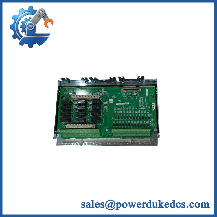
GE IS230TNSVH3A
Application Scenarios & Pain Points
A wrong interpretation of this part number can create a much larger commissioning problem than a simple missing I/O point. The important issue is the actual TSVCH/PSVOH assembly installed in the Mark VIe cabinet.
Gas Turbine Control
In a gas-turbine application, dense discrete signals can reduce cabinet space and wiring count. With 64 documented field points across the combined input/output arrangement, a single module-level problem can affect numerous status and command circuits at once.
Servo and Actuator Interface
For actuator-related control, transistor outputs are used for discrete switching functions rather than direct high-power motor control. Before replacement, confirm the load characteristics, external supply arrangement, and protection devices.
Combined-Cycle Power Generation
During a forced outage, the main pain point is often identification rather than physical replacement. When several discrete points fail together, compare controller diagnostics against the field terminal assembly before replacing downstream devices.
Skid-Mounted Turbine Systems
Compact turbine packages frequently use dense local I/O. In an enclosure reaching 50°C+, inspect ventilation, terminal connections, and DC supply stability before assuming that a failed module has an internal electronic fault.
Balance-of-Plant Control
The Mark VIe platform extends beyond the turbine itself into BOP equipment. This module can therefore appear in systems where the field function looks unrelated to turbine sequencing; the cabinet drawing and I/O database are the authoritative source for channel purpose.
🚨 Common Error Codes & Diagnostic Symptoms
Symptom/Code: Multiple discrete points fail simultaneously
→ Diagnosis: A common I/O-pack, terminal-board, DC supply, or communication issue is more likely than simultaneous independent field-device failures.
→ Action: Verify supply, IONet status, terminal connections, and controller diagnostics; replace the module if the fault follows the assembly.
Symptom/Code: I/O module reports Attention/Fault condition after power-up
→ Diagnosis: Possible hardware fault, configuration mismatch, communication loss, or incorrect associated terminal-board identification.
→ Action: Review controller diagnostics and module identity; substitute a known-good unit after field wiring and power checks.
Symptom/Code: Inputs read inactive while field voltage is confirmed present
→ Diagnosis: Possible input-channel circuitry, common reference, terminal connection, or module-interface failure.
→ Action: Verify the signal at the terminal board and module interface; replace the module after isolating the field circuit.
Symptom/Code: Output command is present in the controller but field actuator does not respond
→ Diagnosis: Check the output transistor path, external field supply, load protection, and wiring before condemning the I/O hardware.
→ Action: Perform a controlled output-load test and replace the module if its output stage fails verification.
🚨 Cross-Reference & Lifecycle Migration
Cross-Reference
- is publicly associated with the TSVCH1A / PSVOH1B(3X) module designation.
- Some supplier records identify it as a digital input module, while others describe the same catalog number as a combined digital I/O or servo module. This is a documentation inconsistency that should not be ignored.
- The complete installed assembly should be identified from the cabinet drawing, terminal-board label, and original GE bill of material.
- Do not substitute an IS230-series module solely because its connector appears mechanically similar.
- Confirm channel count, field voltage, output load requirements, and ControlST configuration before approval.
Firmware and Configuration
A replacement Mark VIe I/O assembly may require the correct system configuration to be downloaded from the controller environment. Do not assume that a physically identical spare contains the exact project configuration required by the site.
For an installed system, record the existing I/O database, firmware information, terminal-board identity, and channel mapping before replacing the hardware.
Lifecycle Status
Status: Legacy / availability-dependent
The practical stocking policy should reflect installed population and criticality. For a turbine cabinet with no readily available equivalent in local inventory, one fully tested spare is considerably more useful than an unidentified board held without configuration records.
A migration project should evaluate the complete I/O architecture rather than replacing only the module designation. Firmware, terminal-board wiring, cabinet density, network topology, and field-load requirements all need review.
Field Engineer’s Tech Notes
Warning 1 — Do not trust the online product description.
This particular catalog number is a good example of why supplier metadata can be misleading. One source labels it a digital input module; another describes a 32-in/32-out assembly. Before ordering a replacement, photograph the nameplate and verify the exact installed TSVCH/PSVO assembly.
Warning 2 — Never connect an unknown field load directly to an unverified transistor output.
Check the actuator or relay load current, external 24 VDC supply, polarity, suppression components, and common reference first. A module can pass a simple continuity check and still fail under the actual field load.
During handling, keep the assembly inside ESD protection until the replacement procedure begins. Connector damage and static discharge are avoidable failure modes, especially with older warehouse stock.
Strict QA & Testing SOP
Step 1 — Inbound Identity Check
Capture:
- GE manufacturer marking
- catalog number
- / designation
- Serial number
- Revision information
- Any associated terminal-board identifiers
Photograph both the nameplate and connector faces.
Step 2 — Physical Examination
Inspect for:
- Cracked housing
- Bent connector contacts
- Oxidation
- Corrosion
- Moisture evidence
- Damaged mounting hardware
- Contaminated terminal interfaces
Step 3 — DC Power Test
Apply the applicable Mark VIe I/O-pack power under controlled test conditions. Verify startup behavior, supply stability, and abnormal current draw.
Step 4 — Controller Communication Test
Using an approved Mark VIe test environment:
- Establish the IONet connection.
- Confirm module recognition.
- Check diagnostic status.
- Verify identification data.
- Confirm no persistent communication faults.
Step 5 — Digital Input Testing
Apply controlled 24 VDC input conditions across representative channels, then verify:
- ON/OFF recognition
- Input stability
- Channel isolation behavior where applicable
- Debounce response
- Diagnostic reporting
For a full acceptance test, exercise every available input channel.
Step 6 — Digital Output Testing
Drive each applicable output through a controlled resistive or approved test load. Record:
- Command state
- Output voltage
- Load response
- Switching stability
- Fault behavior
Do not connect production actuators during warehouse testing.
Step 7 — Extended Run
Operate the module under representative load conditions and monitor:
- Supply stability
- Internal temperature trend
- Communication continuity
- Input-state stability
- Output switching behavior
Step 8 — Final QC Record
The released asset should carry a test file containing:
- Catalog number
- Serial number
- Hardware revision
- Test date
- Test technician
- Power test results
- Communication test results
- Input test results
- Output test results
- Final disposition
Step 9 — ESD Packaging
After passing inspection, place the unit in an ESD-safe antistatic bag with suitable shock and moisture protection. Attach the QC identification to the package so its tested status is preserved in warehouse storage.
Test videos are available when visual evidence is included with the specific unit’s inspection package.
Buyer’s FAQ
A: Do not assume that it is safe to remove the assembly under power. Mark VIe supports controlled online maintenance functions in appropriate configurations, but the exact replacement procedure depends on the installed I/O architecture, field loads, and site safety controls.
Q: Is this a New Original GE module?
A: The catalog number alone does not establish condition. Request clear nameplate photographs, serial-number information, manufacturing traceability, and a test record. “New Original” should be supported by evidence rather than appearance.
Q: Why do some listings call a digital input module while others call it a servo module?
A: The public references are inconsistent because the catalog number is associated with the /(3X) assembly and different databases classify the functional block differently. The installed system drawing and actual nameplate should be treated as authoritative.
Q: What warranty should I require?
A: Request the warranty term in writing and tie it to the serial number and supplied condition. For a critical turbine spare, a useful warranty package should include documented functional testing covering DC power, communication, digital inputs, and digital outputs where applicable.











 Start Chat


