

Description
- Model: IS400SRLYS2ABB
- Brand: General Electric
- Series: Mark VIeS Functional Safety System
- Part Type: Simplex Relay Contact Output Terminal Board
- Core Function: Interfaces 12 discrete relay-contact outputs between the Mark VIeS safety logic and field actuators.
- I/O Architecture: Simplex, using one IS420YDOAS1B discrete-output I/O pack mounted directly on the terminal board. GE documentation identifies the associated terminal-board part as IS410SRLYS2A.
- Relay Capacity: 12 Form-C relay outputs through 48 customer terminals.
- Safety Position: The SRLYS2A design is identified by GE as IEC 61508 compliant, with Class 1 Division 2 / Class 2 Zone 2 / ATEX hazardous-location capability in the specified Mark VIeS system.
- Important Identity Note: Current GE documentation uses IS410SRLYS2A for the SRLY terminal board. IS400SRLYS2ABB appears in supplier records as an associated/legacy ordering identifier, so the complete physical nameplate and system BOM should be checked before purchasing.
Product Introduction
In a safety-control cabinet, a relay terminal board is not just a wiring convenience. The output contacts may sit directly in the path of turbine valves, solenoids, permissives, and shutdown-related actuators. A relay-board failure can therefore remove several discrete output paths at once.
The IS400SRLYS2ABB is identified in current technical documentation with the SRLY architecture used by GE’s Mark VIeS Functional Safety System. The corresponding IS410SRLYS2A provides 12 Form-C relay outputs and accepts one IS420YDOAS1B YDOA I/O pack (the I/O pack is ordered separately).
Core Technical Specifications
| Parameter | Value |
|---|---|
| Manufacturer | General Electric |
| Legacy / Associated Part Number | IS400SRLYS2ABB |
| Current Terminal Board Identifier | IS410SRLYS2A |
| Series | Mark VIeS Functional Safety System |
| Functional Type | Simplex Relay Contact Output Terminal Board |
| Product Function | Mark VIeS Form-C relay output |
| I/O Pack | IS420YDOAS1B, quantity 1 |
| I/O Pack Redundancy | Simplex |
| Number of Channels | 12 |
| Relay Type | Form-C |
| Discrete Outputs | 12 DO |
| Customer Terminals | 48 |
| Contact Rating | 0.6 A @ 125 VDC; 1.2 A @ 48 VDC; 2.25 A @ 24 VDC; 2.25 A @ 120/240 VAC |
| Standard Contact Configuration | Dry Form-C contacts, no fuse |
| Field Terminal Style | Euro-style box-type terminal blocks |
| Field Wire Range | 24 AWG minimum to 12 AWG maximum |
| I/O Pack Control Power | 24/28 VDC |
| Maximum I/O Pack Power | 19.8 W, including output-relay coil drive |
| Diagnostics | Power-up self-test, I/O pack health, commanded-output vs. feedback checking, incorrect-terminal-board detection |
| SOE | Configurable for relay feedback sequence-of-events |
| Output Line Monitoring | No |
| Safety Rating | IEC 61508 compliant |
| Hazardous Location Capability | Class 1 Div. 2 / Class 2 Zone 2 / ATEX, within specified system configuration |
| G3 Compliant | Yes |
| Operating Temperature | -40°C to +70°C |
| Storage Temperature | -40°C to +85°C |
| Mounting | DIN rail |
| Module Dimensions, including cover and I/O pack | 17.0 × 24.9 × 15.3 cm (H × W × D) |
The specifications above come from GE’s Mark VIeS technical documentation rather than generic relay-board listings. The 19.8 W maximum applies to the I/O pack/control assembly and includes power needed to drive the output relay coils.
A practical procurement point: the IS400SRLYS2ABB identifier is repeatedly associated in current supplier catalogs with IS410SRLYS2A, while GE’s newer system documentation formally lists IS410SRLYS2A as the terminal-board part. Treat this as an ordering cross-reference, not automatic proof that every physical IS400-labeled assembly is identical.
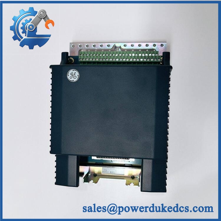
GE IS400SRLYS2ABB
Application Scenarios & Pain Points
For turbine safety-system actuator control, the SRLY provides twelve Form-C relay paths for discrete field actuators. The simplex architecture is appropriate where the application does not require TMR output hardware at that terminal-board position.
When a solenoid or relay circuit begins showing inconsistent feedback, inspect both sides of the interface. The terminal board provides isolated relay-contact feedback to the YDOA pack, allowing the control logic to compare commanded output with observed relay state.
At sites operating near 70°C cabinet temperature, the documented operating range extends to +70°C, but heat accumulation inside a tightly packed cabinet still deserves attention (especially where multiple energized relay coils are present).
During functional-safety maintenance, the important distinction is between the terminal board and the I/O pack. The SRLY terminal board is ordered separately from the IS420YDOAS1B pack; purchasing one does not automatically provide the other.
For legacy Mark VIeS installations, maintaining an accurately identified spare can prevent an avoidable outage caused by confusing an SRLY board with a TRLY TMR board. The two architectures should not be substituted simply because both use relay contacts.
Common Error Codes & Diagnostic Symptoms
Symptom/Code: Incorrect Terminal Board / Hardware Compatibility Fault
→ Diagnosis: The YDOA pack detects that the connected terminal-board identity does not match the expected configuration. GE explicitly documents incorrect-terminal-board detection.
→ Action: Verify the terminal-board identity, I/O pack identity, and ControlST configuration before replacing the board.
Symptom/Code: Commanded Output Does Not Match Relay Feedback
→ Diagnosis: A failed relay, open field circuit, damaged terminal connection, or terminal-board sensing problem can produce a mismatch between the commanded state and relay feedback.
→ Action: Check field wiring and relay contacts under controlled conditions; replace the affected hardware after confirming board-level failure.
Symptom/Code: Loss of I/O Pack Health / Power-Up Diagnostic Fault
→ Diagnosis: Possible YDOA pack, power-supply, communication, or terminal-board problem. The SRLY documentation specifically lists power-up self-test and I/O-pack health diagnostics.
→ Action: Check 24/28 VDC supply, pack status, connector seating, and configuration before condemning the terminal board.
GE’s public SRLY documentation does not establish a universal numeric fault-code list for this specific assembly. Use the actual Mark VIeS ControlST diagnostic message and approved site alarm database for exact numeric interpretation.
Cross-Reference & Lifecycle Migration
IS400-to-IS410 Identification
The most important procurement relationship is:
Current Mark VIeS technical documents identify as the SRLY terminal-board part number, while supplier databases list IS400SRLYS2ABB as an associated or legacy identifier.
That means a purchasing department should place both identifiers on the sourcing record, but acceptance should still be based on the actual hardware marking and configuration.
Functional Replacement
The current documented SRLY assembly uses:
IS410SRLYS2A + IS420YDOAS1B
The YDOA I/O pack is not integrated into the terminal-board ordering number and is ordered separately.
Do Not Cross to TRLY Without Engineering Review
SRLY is a simplex relay-output architecture. TRLY is associated with TMR relay-contact output arrangements. Moving from one to the other changes the system topology and safety architecture, so it is not a routine drop-in substitution.
Firmware
The SRLY terminal board itself is primarily a passive/interface assembly. Firmware resides in the associated IS420YDOAS1B I/O pack rather than being a standalone firmware-bearing terminal board. Therefore, any firmware compatibility check should be performed against the YDOA pack and the Mark VIeS ControlST baseline.
Lifecycle Status
Current documented SRLY terminal board status: Active for in GE’s Mark VIeS documentation.
For inventory purposes, should be treated as a legacy/associated ordering identifier until the physical unit and current GE BOM are reconciled. Do not build safety-stock records around the IS400 number alone.
Field Engineer’s Tech Notes
Warning 1 — The board and YDOA pack are separate orderable items.
A replacement shipment containing only the SRLY terminal board is incomplete if the failed asset is the complete terminal-board/I/O-pack assembly. GE explicitly lists as the I/O-pack replacement part and as the terminal-board part.
Warning 2 — Watch the relay load calculation.
Do not copy a generic “relay output” rating into the commissioning worksheet. GE specifies different limits for 24 VDC, 48 VDC, 125 VDC, and 120/240 VAC. Inductive loads and solenoids require special attention to their actual operating and inrush characteristics.
One more point from field maintenance: verify the 48 customer-terminal mapping before rewiring. Similar-looking GE relay terminal boards can have different channel assignments even when the front-panel footprint appears familiar.
Strict QA & Testing SOP
Step 1 — Inbound identity check
Record , the associated identifier where present, serial/date information, packaging labels, and the installed YDOA pack number.
Step 2 — Physical inspection
Inspect the DIN-rail mechanism, cover, terminal blocks, relay area, board connectors, and mounting hardware. Look for damaged terminal screws, cracked housings, corrosion, contamination, or evidence of overheating.
Step 3 — Assembly verification
Confirm whether the shipment is the terminal board alone or a complete assembly containing the . Never record these as the same inventory item.
Step 4 — Electrical inspection
Verify the specified control-power arrangement and inspect relay-contact circuits against the approved wiring diagram. Do not exceed the documented contact ratings.
Step 5 — Relay functional testing
Using a controlled test fixture, command each of the 12 relay channels and verify contact transfer between the appropriate Form-C terminals.
Step 6 — Feedback testing
Confirm that the YDOA correctly observes relay state and that commanded-output versus feedback diagnostics behave as expected.
Step 7 — Diagnostic testing
Verify power-up self-test, I/O-pack health, electronic identification, and incorrect-terminal-board diagnostics.
Step 8 — Safety configuration check
For safety applications, verify the exact hardware combination against the approved Mark VIeS safety configuration before releasing the spare.
Step 9 — Final QA and packaging
Record test values, relay-channel results, serial numbers, technician sign-off, and inspection photographs. Package the assembly in ESD-safe protection with mechanical cushioning. Test videos are available with the QC record when required for procurement verification.
Buyer’s FAQ
A: Do not assume live replacement is permitted. This board sits in a functional-safety relay-output path, and the associated YDOA pack and field actuators may be affected by removal. Follow the site’s approved Mark VIeS maintenance procedure and verify the safety state before disconnecting the assembly.
Q: Is the same part as ?
A: Current GE Mark VIeS documentation identifies as the SRLY terminal-board part, while commercial records explicitly associate with . Because naming varies across legacy documentation and supplier databases, verify the physical nameplate and system BOM before purchase.
Q: How do I verify a New Original unit?
A: Request clear photographs of the GE label, complete part number, serial/date information, terminal-board markings, and any installed YDOA pack. For a safety-system spare, also retain the COO, test report, and packaging evidence with the receiving record.
Q: What warranty should I require?
A: Require written DOA and functional-failure coverage tied to the unit serial number. For a safety-related relay board, the supplier should also provide the pre-shipment test record and a defined return/replacement procedure.











 Start Chat


