

Description
- Model: GE IS400STCIS2AFF
- Current Assembly Identity: IS410STCIS2A
- Brand: General Electric
- Series: Mark VIeS Functional Safety System
- Part Type: STCI 24 VDC Contact Input Terminal Board
- Core Function: Provides the field termination and contact-wetting interface for 24 discrete safety inputs, working with one IS420YDIAS1B Safety Discrete Input I/O Pack.
- Key Specs: 24 contact-input channels, 24 VDC nominal wetting voltage, 110 mA source capacity, 20–32 VDC wetting range, 1 ms SOE sampling, simplex architecture, DIN-rail mounting, and IEC 61508 safety qualification.
Product Introduction
IS400STCIS2AFF is the internal/replacement-board ordering identity associated with GE’s IS410STCIS2A terminal-board assembly. The current GE Mark VIeS documentation identifies the complete assembly as IS410STCIS2A, described as a Simplex, 24-point, 24 VDC contact-input terminal board. The IS400STCIS2A board is the internal replacement board within that assembly.
At the field interface, this hardware handles 24 discrete contact inputs and supplies the required floating contact-wetting voltage. It is designed to work with the IS420YDIAS1B safety discrete-input I/O pack (ordered separately). That distinction is essential during procurement: the STCI terminal board and YDIA I/O pack are separate orderable components, although they operate as one functional I/O module.
Core Technical Specifications
| Parameter | Value |
|---|---|
| Manufacturer | GE General Electric |
| Current Assembly Model | IS410STCIS2A |
| User-Supplied Ordering Identifier | IS400STCIS2AFF |
| Internal Replacement Board | IS400STCIS2A |
| Series | Mark VIeS |
| Functional Acronym | STCI |
| Product Type | Safety Contact Input Terminal Board |
| Application | 24 VDC discrete/contact input |
| I/O Architecture | Simplex |
| Number of Channels | 24 inputs |
| Compatible I/O Pack | IS420YDIAS1B |
| Input Wetting Voltage | 24 VDC nominal |
| Wetting Voltage Range | 20–32 VDC |
| Wetting Source | Floating source for ground-fault detection |
| Wetting Current | 110 mA |
| SOE Capability | 1 ms sampling rate |
| Contact Input Line Monitoring | No |
| Diagnostic Detection | Power-up self-test, loss of contact-input voltage, non-responding contact input, incorrect terminal-board detection |
| Field Wiring | Euro-style box terminal blocks |
| Supported Wire Size | 24 AWG minimum to 12 AWG maximum |
| I/O-Wetting Power Connector | Mate-N-Lok receptacle, AMP 350766-1 |
| I/O-Pack Control Power | 24/28 VDC |
| I/O-Pack Maximum Power | 6.8 W for IS420YDIAS1B |
| Enclosure | Aluminum I/O-pack case |
| Assembly Dimensions | 17.0 × 15.7 × 15.3 cm H × W × D, including cover and I/O pack |
| Mounting | DIN rail |
| Operating Temperature | -40°C to +70°C |
| Storage Temperature | -40°C to +85°C |
| G3 Environmental Compliance | Yes |
| Safety Rating | IEC 61508 compliant |
| Hazardous-Area Capability | Class I Division 2 / Class II Zone 2 / ATEX configuration |
| Standalone Firmware | None |
| Lifecycle | Active assembly: IS410STCIS2A |
Important part-number distinction
For purchasing records, use the relationship:
IS400STCIS2AFF → IS410STCIS2A assembly → IS400STCIS2A internal replacement board
Do not interpret these identifiers as three independent functional modules. The is the complete current terminal-board assembly, while IS400STCIS2A identifies the replacement board used within it.
The associated IS420YDIAS1B provides the active safety I/O processing. The STCI hardware performs field termination and contact-input interfacing rather than running application firmware itself.
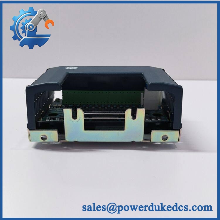
GE IS400STCIS2AFF
Application Scenarios & Pain Points
Turbine safety interlocks: A Mark VIeS installation can use the 24 input channels for discrete contacts representing permissives, shutdown conditions, breaker status, valve position, and other safety-related field states. The floating 24 VDC wetting source helps support ground-fault detection.
Power-generation auxiliary protection: Contact inputs from generators, pumps, valves, and auxiliary equipment can be consolidated through the STCI terminal assembly. A failed wetting supply can affect multiple channels at once, so technicians should test the common supply before replacing individual field devices.
Emergency shutdown circuits: The 1 ms SOE sampling capability is valuable where the sequence of discrete events matters during a trip investigation. It records contact-state timing through the safety I/O architecture rather than relying only on slower supervisory indications.
Hazardous-area turbine cabinets: The STCI assembly can be used within documented Class I Division 2, Zone 2, and ATEX configurations. Certification depends on the specified equipment combination, installation conditions, and applicable certification documentation.
Brownfield safety migration: Plants retaining older Mark VIeS contact-input infrastructure may encounter the IS400STCIS2AFF identifier on engineering drawings or procurement records while newer GE documentation identifies the complete assembly as . At a 50°C+ cabinet ambient, connector condition, contact-wetting voltage, and enclosure ventilation should all be checked during a replacement.
🚨 Common Error Codes & Diagnostic Symptoms
Symptom/Code: Loss of contact-input voltage
→ Diagnosis: The STCI/YDIA combination is no longer receiving the expected contact-wetting voltage. A power-distribution fault, wiring problem, terminal issue, or common supply fault can affect several inputs simultaneously.
→ Action: Measure the wetting voltage at the terminal board and verify the field circuit before replacing the board.
Symptom/Code: Non-responding contact input detected during background testing
→ Diagnosis: The input circuit may not respond as expected during the YDIA diagnostic routine. Possible causes include an open field circuit, incorrect contact wiring, inadequate wetting voltage, or an input-channel hardware fault.
→ Action: Isolate the field circuit, verify the expected contact state, and replace the defective I/O component only after controlled testing.
Symptom/Code: Incorrect terminal-board identification/configuration
→ Diagnosis: The connected YDIA pack does not recognize the expected STCI terminal-board configuration. This can result from an incorrect terminal board, hardware-revision mismatch, connector problem, or system configuration error.
→ Action: Verify , the associated IS420YDIAS1B, and the approved Mark VIeS hardware configuration.
The exact diagnostic identifier shown by the controller depends on the installed Mark VIeS software and ControlST revision. The terminal board itself does not have a universal standalone numerical error-code set.
🚨 Cross-Reference & Lifecycle Migration
Lifecycle Status:
GE’s current Mark VIeS functional-safety documentation lists . The corresponding safety contact-input I/O pack is , ordered separately.
Compatibility and migration data
- IS400STCIS2AFF: Engineering/procurement identifier associated with the STCI terminal-board design.
- Current complete simplex 24 VDC STCI terminal-board assembly.
- IS400STCIS2A: Internal replacement board specified within the assembly.
- Current safety discrete-input I/O pack used with the .
- IS220YDIAS1A: Earlier Mark VIeS safety discrete-input I/O-pack generation. Its compatible legacy terminal boards include earlier STCI assemblies such as IS400STCIS2A-family hardware.
- Migration path: GE’s current architecture moves the active safety contact-input combination toward .
- Firmware: The terminal board contains no standalone application firmware. Firmware management applies to the associated YDIA I/O pack and Mark VIeS controller environment.
- Simplex versus TMR: is a simplex terminal-board configuration. Do not substitute a TBCIS TMR terminal board merely because it also provides 24 contact inputs.
- Buffer-stock strategy: Because the current IS410 assembly remains active, normal replenishment is feasible. For safety-critical sites, one verified complete assembly plus the correct YDIA spare provides better coverage than stocking an unidentified bare board.
Field Engineer’s Tech Notes
Warning 1 — Do not mistake a 24 VDC STCI board for a generic dry-contact terminal block.
The STCI/YDIA combination supplies a defined 20–32 VDC floating contact-wetting source. Replacing it with a passive terminal assembly can change how the safety input circuit is electrically supervised.
Warning 2 — Confirm the exact procurement identity before installation.
If the drawing says while the current GE replacement is labeled , reconcile the two identifiers in the maintenance record before disconnecting anything. Never infer equivalence from the name alone, particularly when a safety-certified assembly is involved.
Strict QA & Testing SOP
Step 1 — Inbound identity inspection
Verify , internal board identity where visible, assembly revision, serial/traceability markings, cover, terminal blocks, and mounting hardware.
Step 2 — Configuration inspection
Confirm that the assembly is the 24 VDC simplex STCI configuration, not the related 48 VDC STCI or 125 VDC contact-input variant.
Step 3 — Mechanical examination
Inspect the DIN-rail mechanism, enclosure, terminal blocks, Mate-N-Lok connector, terminal screws, and I/O-pack mounting interface.
Step 4 — Continuity testing
Verify each field terminal path through the approved wiring diagram. Check for unintended shorts between input, return, wetting supply, and shield/reference points.
Step 5 — Contact-wetting test
With an approved test setup, verify approximately 24 VDC nominal wetting voltage and confirm that the source remains within the 20–32 VDC specified operating range.
Step 6 — Channel simulation
Connect controlled contact simulators to all 24 input channels. Exercise open and closed states and verify stable recognition through the associated .
Step 7 — Diagnostic testing
Test representative loss-of-wetting, non-responding-input, and terminal-board-identification conditions using the approved Mark VIeS test environment.
Step 8 — SOE verification
Where the test setup supports it, verify the 1 ms SOE sampling behavior and record event timing against the test fixture.
Step 9 — Safety configuration review
Confirm the YDIA hardware revision and approved Mark VIeS software/configuration baseline. Do not introduce an unverified firmware revision into a safety system.
Step 10 — QA documentation and packaging
Record channel results, wetting voltage, hardware identity, serial/traceability information, photographs, and final QC status. Test videos are available as supporting inspection evidence when requested. Package the assembly in ESD protection with connector and terminal protection for international transportation.
Buyer’s FAQ — Dynamic Q&A
Q: Can the / be hot-swapped?
A: Do not assume live replacement. This is part of a Mark VIeS safety contact-input system. Follow the approved GE maintenance and site isolation procedure before disconnecting the terminal assembly or associated YDIA pack.
Q: Why does my drawing show while the newer documentation says ?
A: is associated with the earlier/internal board identification, while is the current complete terminal-board assembly designation. Purchasing should reconcile the old drawing number with the current assembly identity before ordering.
Q: How can I verify a New Original unit?
A: Check the complete assembly identity, revision markings, terminal-board construction, DIN-rail hardware, cover, serial/traceability information, and documented QA results. For safety inventory, confirm that the supplied assembly is genuinely the 24 VDC STCI configuration and not the visually similar 48 VDC or 125 VDC variant.
Q: What warranty should I require?
A: Require a written warranty tied to the supplied serialized assembly and its tested condition. The procurement record should include the exact part-number relationship, inspection report, measured contact-wetting voltage, functional test results, traceability information, and warranty start date from receipt.











 Start Chat


