

Description
- Brand: GE
- Full Model Number: MPU55
- Common Catalogue Number: MPU55-CBAUS / MPU55-CBACN
- System/Series Family: Nexus OnCore
- Core Function: Controller module for Nexus OnCore programmable control and I/O systems
- Top 3 Hardcore Specs: 21.6–26.4 VDC supply | 7.2 W maximum rated power | Controller module
- Hazardous-Area Variants: CBAUS / CBACN
- Stock Status: New surplus, factory sealed, or fully tested refurbished subject to exact inventory confirmation
GE documentation identifies MPU55 as a Nexus OnCore Controller Module. The official GE documentation lists MPU55-CBAUS and MPU55-CBACN variants with a 21.6–26.4 VDC supply range and 7.2 W power rating.
Module 3: Technical Product Introduction
A controller failure in a Nexus OnCore installation can affect the execution of the control application and the associated I/O architecture. The GE MPU55 serves as the controller module within the Nexus OnCore platform, rather than functioning as a conventional standalone analog or digital I/O card. GE’s own documentation identifies the MPU55 alongside other OnCore controller modules and lists both MPU55-CBAUS and MPU55-CBACN variants.
Electrical requirements are straightforward but should not be overlooked during replacement. GE documentation specifies 21.6–26.4 VDC and 7.2 W for the MPU55 controller module. That places the nominal supply around 24 VDC, while the permitted range gives the maintenance engineer a defined power window for the installation check. The module is also included in GE’s hazardous-area certification documentation, so the exact catalogue suffix matters when the controller is installed in a classified environment.
Module 4: Application Scenarios & Field Realities
- In Nexus OnCore control cabinets, the MPU55 acts as the controller rather than a field-signal termination card. If the controller fails, check the 24 VDC supply, module status, and associated I/O communication before replacing the hardware.
- For hazardous-area installations, the exact catalogue suffix is important. GE documentation separately identifies MPU55-CBAUS and MPU55-CBACN, and the MPU55 is included in GE’s hazardous-area certification documentation. Do not substitute a non-matching variant simply because the basic MPU55 designation is identical.
- During a planned controller replacement, preserve the existing application configuration and document the installed module’s complete catalogue number before removal. The replacement hardware may be physically correct while still requiring configuration restoration before the control system can resume normal operation.
- Where multiple OnCore modules share the same 24 VDC supply, verify the cabinet power budget before commissioning. GE lists 7.2 W for the MPU55, while neighboring OnCore modules have different consumption figures. The power-supply check should therefore cover the complete module assembly, not just the controller.
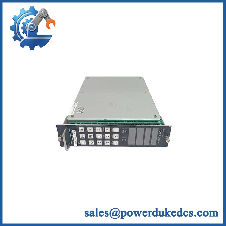
GE MPU55
Module 5: Migration, Compatibility & Installation Traps
Replacement Matrix
| Replacement Type | Assessment | Engineering Requirement |
|---|---|---|
| Drop-in Replacement | Potentially yes for an identical MPU55 variant | Match complete catalogue number, certification variant, revision, and system configuration |
| Software Compatible | Configuration-dependent | Restore and verify the existing OnCore application and controller configuration |
| Hardware Modification Required | Not normally required for an exact replacement | Confirm mounting, connector arrangement, power supply, and I/O architecture |
Field Traps — Watch Out
1. CBAUS vs. CBACN: GE documentation identifies both MPU55-CBAUS and MPU55-CBACN. These suffixes should not be ignored when the controller is installed in a certified or regulated environment. Match the complete catalogue number against the original unit and site certification requirements.
2. 24 VDC supply tolerance: The specified supply range is 21.6–26.4 VDC. Measure the voltage at the module terminals under load rather than relying on the nominal power-supply label. A cabinet can show 24 VDC at the power supply while experiencing a lower voltage at the controller because of wiring resistance or a failing distribution connection.
3. Configuration restoration: Replacing the physical controller does not automatically restore the application configuration. Before removing a functioning MPU55, preserve the available application and controller data using the approved GE procedure for the installed OnCore system.
4. Hazardous-area installation: Where the MPU55 is installed in a classified area, maintenance must follow the site’s hazardous-area isolation procedure and the applicable GE certification requirements. Do not treat a standard cabinet replacement procedure as sufficient for an Ex installation.
Module 6: Quality Assurance SOP
Before shipment, each GE MPU55 should undergo a documented inspection sequence appropriate to the available Nexus OnCore test equipment.
- Step 1 — Part-number verification: Record MPU55, the complete catalogue number such as MPU55-CBAUS or MPU55-CBACN, serial number, revision markings, and all visible GE identification.
- Step 2 — OEM anti-counterfeit visual inspection: Examine GE labels, printing quality, PCB markings, connectors, housing, fasteners, and manufacturing identifiers. Photograph the complete nameplate and catalogue number.
- Step 3 — Physical condition inspection: Check the controller for corrosion, contamination, cracked components, damaged connectors, bent contacts, loose hardware, and evidence of unauthorized repair or rework.
- Step 4 — DC power verification: Confirm the test supply is within the specified 21.6–26.4 VDC range before energizing the module. Record the measured voltage at the test fixture.
- Step 5 — Power-on self-test (POST): Energize the MPU55 under controlled conditions and record startup behavior, diagnostic indicators, controller status, and any reported fault condition.
- Step 6 — Controller function verification: Where the appropriate Nexus OnCore test environment is available, confirm that the MPU55 initializes correctly and performs its expected controller functions.
- Step 7 — Communication handshake verification: Verify communication between the MPU55 and the associated OnCore modules or test equipment. Confirm that connected I/O modules are recognized as expected.
- Step 8 — Power-consumption check: Where test equipment permits, verify that operating consumption is consistent with the documented 7.2 W maximum rating under the applicable test condition.
- Step 9 — Certification identification check: For CBAUS/CBACN variants, verify that the physical identification corresponds to the required certified configuration before release.
- Step 10 — Final photographic record: Photograph the complete controller, catalogue label, serial/reference markings, connectors, and packaging condition.
QA release criterion: The MPU55 should not be described as fully system-tested unless the controller, communication interfaces, and associated OnCore architecture have actually been tested. A successful power-up alone confirms basic electrical operation; it does not establish complete application-level functionality.











 Start Chat


