

Description
- Brand — GE Fanuc / VMIC
- Full Model Number — VMIVME-2170A
- System/Series Family — VMIVME VMEbus Digital I/O
- Core Function — 32-channel optically isolated digital output interface for VMEbus control systems
- Top 3 Hardcore Specs — 32 optically isolated outputs; 5–30 VDC I/O voltage range; 2.5 mA or 300 mA output configurations
- Stock Status — New Surplus; exact physical stock and hardware revision to be confirmed
Technical Product Introduction
When a legacy VME controller must drive solenoids, relays, lamps, contactors, or other discrete loads, isolation between the computer bus and field wiring becomes a critical maintenance concern. The GE Fanuc VMIVME-2170A is a dedicated 32-channel optically isolated digital output board for VMEbus systems. Four 8-bit output registers provide the field interface, while optical couplers isolate the 32 output channels from the VMEbus and from one another. The board accepts both 8-bit and 16-bit VMEbus data transfers and can operate with supervisory or nonprivileged short I/O transfers.
The electrical figures are more useful than a generic “high-speed I/O” description. GE documentation specifies 5 to 30 VDC output operation, with 2.5 mA or 300 mA output options, depending on the hardware configuration. The board also provides externally supplied pull-up voltage, field-configurable pull-up resistors, source or sink capability with the low-current option, and isolation rated at 1 kV sustained and 6 kV pulsed. On-board DIP switches provide 14-bit board address selection.
Application Scenarios & Field Realities
- For machine-control cabinets built around a VME CPU, the VMIVME-2170A can handle a dense set of discrete output commands from one board. Thirty-two isolated channels are suitable for valve commands, interposing relays, actuator enables, alarm annunciators, and other binary loads where field-side voltage must remain separated from the VME electronics.
- In electrically noisy equipment, optical isolation helps prevent field transients and ground-potential differences from coupling directly into the VME control electronics. GE specifically lists elimination of system ground loops and control in high-electrical-noise environments among the board’s intended applications.
- Where several external potentials must be controlled from one VME chassis, the externally supplied pull-up arrangement can be useful because the field-side supply does not have to be taken directly from the VMEbus. The exact output wiring, however, must follow the selected source/sink configuration and the installed load characteristics.
- During legacy VME refurbishment, the -2170A is most valuable as an exact hardware replacement rather than as a generic digital-output substitute. Its 14-bit address selection, output polarity options, external pull-up arrangement, and 64-pin front I/O connector all form part of the installed system’s interface definition.
Migration Compatibility & Installation Traps
Replacement Matrix
| Replacement Case | Classification | Engineering Requirement |
|---|---|---|
| VMIVME-2170A replacing the same VMIVME-2170A configuration | Drop-in Replacement | Match board revision, output-current option, polarity, address settings, connector wiring, and chassis configuration |
| VMIVME-2170A replaced by another VMIC digital-output variant | Software Compatible | Recheck channel count, register mapping, output electrical characteristics, addressing, and driver configuration |
| replaced by a different VME I/O architecture | Hardware Modification Required | Re-engineer field wiring, output interface, addressing, software access, and load-driving circuitry |
The suffix and hardware configuration should not be treated as cosmetic details. The is a specific 32-output architecture, and the board provides selectable electrical characteristics that must agree with the field circuit. A board that fits the VME chassis is not automatically an electrically equivalent substitute.
Field Traps — Watch Out
External pull-up voltage: The uses an externally supplied pull-up voltage to maintain field-side isolation. Verify the external supply voltage and polarity before connecting the I/O cable. The published specification places the normal output voltage range at 5–30 VDC.
Pull-up resistor dissipation: The hardware manual warns that the user-installed DIP pull-up resistors have a 0.1 W power rating. Exceeding that rating can damage the resistor network. The manual also notes that installing these resistors reduces isolation between channels.
Current-option mismatch: Do not assume a 2.5 mA output and a 300 mA output version can be wired identically. Confirm the actual hardware option against the load current and interface circuit before replacing the board.
Front connector pinout: The output interface uses a 64-pin DIN connector, with separate collector and emitter connections for the output channels. Moving the cable without checking the pin assignment can place an output on the wrong field circuit.
Address configuration: The on-board DIP switches provide 14-bit board address selection. Record the original switch positions before removing the failed unit, then verify the replacement against the VME system memory or short-I/O map.
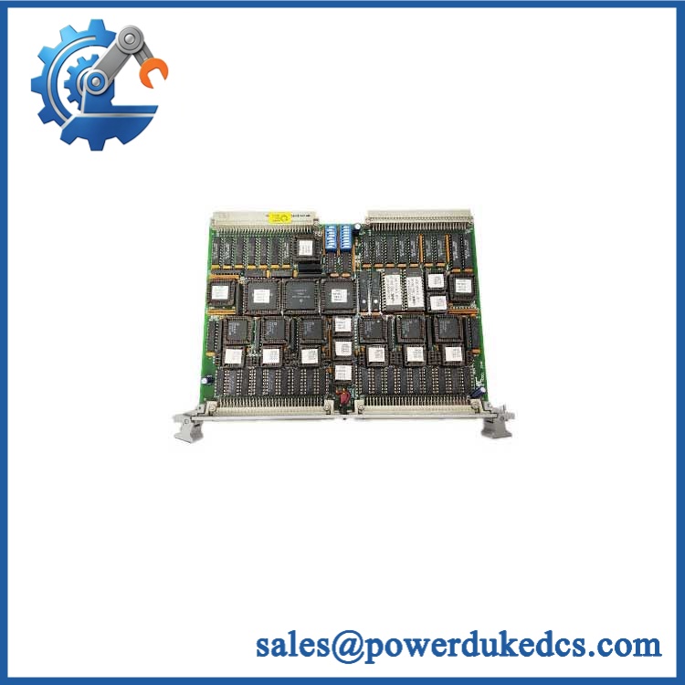
GE VMIVME-2170A
Quality Assurance SOP
The pre-shipment procedure should verify both the VME interface and the field-output circuitry:
- OEM anti-counterfeit visual inspection — compare GE Fanuc/VMIC labeling, model designation, PCB identifiers, revision markings, component population, connector construction, and evidence of unauthorized rework.
- Mechanical inspection — examine the VME edge connector, 64-pin I/O connector, board guides, mounting hardware, PCB surface, and exposed contacts for bent pins, corrosion, contamination, or impact damage.
- Power-on self-test (POST) — install the board in an appropriate VME chassis and verify normal initialization. Check available ERR/RUN or board-status indications where fitted and record abnormal behavior.
- VME host recognition verification — confirm that the host processor can access the configured board address without bus timeout or address-decoding faults.
- Digital output channel test — exercise all available output channels through a controlled VME test program and verify the commanded state at the field connector.
- Isolation verification — confirm electrical isolation between the VME side and output circuits using an approved test procedure and suitable instrumentation.
- Voltage verification — test the output interface within the applicable 5–30 VDC operating range and confirm that the actual hardware configuration matches the sales specification.
- Current-load verification — test the applicable 2.5 mA or 300 mA output configuration under controlled load conditions rather than relying on an unloaded continuity check.
- Polarity and source/sink verification — confirm positive/negative true behavior and source/sink configuration against the intended application.
- Communication handshake verification — issue controlled VME write/read transactions and verify that each output register responds to the correct host command.
- Address and DIP-switch record — document the 14-bit address setting and any installed pull-up resistor configuration before final release.
- Final inspection and packaging — photograph the actual unit, record model and revision information, apply ESD protection, protect the front connector, and package the board for industrial shipment.
For surplus inventory, the meaningful acceptance standard is more than a board that powers up. The test should demonstrate VMEbus recognition, correct addressing, channel-by-channel output operation, and the correct field-side electrical configuration. That approach is especially important for this board because output current, polarity, pull-up circuitry, and connector wiring directly affect the installed load interface.











 Start Chat


