

Description
- Brand: GE / VMIC
- Full Model Number: VMIVME-2540
- System/Series Family: VMIC VME Intelligent Counter/Controller
- One-Sentence Core Function: 24-channel VMEbus slave I/O module for high-speed event counting, frequency measurement, pulse generation, and position control
- Top 3 Hardcore Specs: Up to 4 giga events; frequency measurement up to 2.5 MHz; 24 control/measurement interfaces
- Stock Status: New Surplus / Fully Tested Refurbished subject to actual inventory inspection
Module 3: Commercial-Technical Deep Dive
When a legacy VME system must measure high-speed pulses without adding another external controller, the GE VMIVME-2540 provides the measurement and function-generation hardware directly at the VMEbus level. It is a 24-channel Intelligent Counter/Controller with six programmable System Timing Controllers in its full 24-channel configuration. The module supports event counting, frequency measurement, period and pulse-width measurement, square-wave and pulse-train generation, timer interrupts, and quadrature position measurement. Its 15 MHz 68HC000 local CPU manages the counter/controller functions while the VME host accesses the module through a memory-mapped slave interface.
The numbers matter for motion and instrumentation work. Frequency measurement extends to 2.5 MHz, while period measurement can resolve signals down to 400 ns in supported operating modes. Event counting reaches 4 giga events, and the pulse-generation range extends to 2.5 MHz. The VME interface supports A32/A24 addressing with D32, D16, and D8 data transfers, while the field interface uses RS-422 with support for single-ended TTL inputs. That combination is useful when replacing an installed counter board because the existing VME host can continue exchanging measurement data through the same architectural interface—assuming the channel configuration and application driver remain compatible.
Module 4: Compatibility & Installation Traps
Migration/Compatibility
- Replacement status: Configuration-specific VMIC VME Intelligent Counter/Controller.
- Logic rewrite: Usually not required for a one-for-one replacement when the existing software expects the VMIVME-2540 register and function set.
- Firmware flash: Not automatically required. Record the existing firmware and board configuration before replacement.
- Channel configuration: Ordering information supports 4, 8, 16, or 24 interfaces. Confirm the installed board’s exact channel configuration rather than assuming every VMIVME-2540 has the same populated hardware.
- VME compatibility: The module is a VMEbus slave I/O device supporting A32/A24 addressing and D32/D24/D16/D08 data access.
⚠️ Field Traps (Watch Out)
- RS-422 versus TTL wiring: The front-panel interfaces use differential RS-422 line receivers and drivers, while single-ended TTL operation requires the specified reference connection. Do not copy an RS-422 wiring scheme directly into a TTL installation.
- Channel-option mismatch: A replacement with fewer populated interfaces may fit the same VME chassis while failing application requirements. Confirm the installed channel count and ordering option before dispatch.
- Shared local memory access: The local 68HC000 CPU and VME host share access to local resources. The documented interface arbitrates this access, so application timing should be validated after replacement rather than assuming identical performance from an unverified board revision.
- ESD: Protect the VME connector and exposed circuitry during removal and installation; use grounded ESD handling procedures.
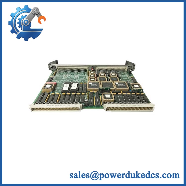
GE VMIVME-2540
Module 5: Quality Assurance SOP
Before shipment, the GE VMIVME-2540 should pass a counter/controller-specific inspection sequence:
- OEM anti-counterfeit visual inspection — verify GE/VMIC markings, model number, PCB identification, front-panel labeling, connectors, and board construction.
- PCB and connector inspection — examine the VME connector, front-panel signal connectors, solder joints, components, and mounting hardware for damage, corrosion, contamination, or unauthorized modification.
- Configuration verification — identify the installed channel configuration and any board-level options against the original unit.
- Power-on self-test (POST) — install the module in a compatible VME test chassis and verify expected startup behavior and processor initialization.
- VMEbus communication handshake — confirm that the host recognizes the module and that expected register/memory access functions operate correctly.
- Counter verification — apply controlled test pulses and verify event-count acquisition using known frequencies and count values.
- Frequency/period verification — test representative signal frequencies and pulse periods against calibrated test equipment.
- Output verification — where supported by the configured hardware, verify square-wave or pulse-train generation under controlled loads.
- Interrupt verification — test applicable VMEbus interrupt functions and confirm correct host acknowledgment behavior.
- Final QC record — document model number, channel configuration, board revision, serial/identification information where available, test conditions, measured results, photographs, and packaging condition.
A counter board that merely passes a power-up check is not fully tested. The meaningful acceptance points are VME communication, pulse measurement, timing accuracy, and output behavior.
Module 6: CRO-Driven Buyer FAQ
1. Is GE VMIVME-2540 obsolete, and how do I verify an authentic replacement?
The is legacy VME hardware from the VMIC product family, later associated with GE and subsequently Abaco Systems. Current manufacturer documentation still identifies the VME-2540 as a 24-channel Intelligent Counter/Controller. For replacement procurement, verify the physical board marking, complete model number, channel configuration, revision, and condition rather than purchasing on the “2540” family number alone.
2. Can I hot-swap the ?
Do not assume hot-swap capability. The is a VMEbus slave I/O module, not a component that should be removed from an energized chassis without an installation procedure explicitly authorizing it. Shut down the applicable system, isolate power, and follow the site’s LOTO and VME maintenance procedures.
3. Will replacing the require rewriting the control application?
Usually not for an identical replacement. The board exposes a defined VMEbus interface and local control architecture, so an unchanged application can generally continue using the same hardware abstraction. The exact driver, address mapping, channel count, and board configuration still need verification before commissioning.
4. What is the maximum measurement frequency?
The published specification gives a 2.5 MHz maximum input frequency for frequency measurement, with square-wave and pulse-train generation also extending to 2.5 MHz. Period measurement supports signal periods down to 400 ns in the specified operating modes.
5. What warranty and technical support are available?
Warranty duration should match the actual stock condition stated on the quotation. Technical support should cover exact model verification, channel-configuration checks, VME compatibility, wiring review, and documented bench-test results. Application-specific timing validation and live machine commissioning remain dependent on the customer’s VME system and process instrumentation.











 Start Chat


