

Description
- Brand: GE Intelligent Platforms / VMIC
- Full Model Number: VMIVME-5565-11000 / 332-015565-110000
- System/Series Family: VME-5565 Reflective Memory
- Core Function: VMEbus reflective-memory node card for deterministic real-time data sharing between distributed systems
- Top 3 Hardcore Specs: 128 MB SDRAM reflective memory; 2.125 Gbaud optical link; 43 to 170 MB/s non-redundant transfer rate
- Stock Status: New Surplus — exact board condition and identification to be verified before shipment
The supplied ordering information corresponds to the VMIVME-5565-110000 configuration: 128 MByte memory with multimode optical transmission. The GE documentation also identifies this family as the VME implementation of its 5565 Reflective Memory architecture.
Module 3: Technical Product Introduction
When a distributed VME control system depends on deterministic data exchange between processors, replacing the reflective-memory interface with an ordinary network card changes the communication architecture rather than simply replacing a failed board. The GE VMIVME-5565-110000 is a VMEbus reflective-memory node card designed to make data written to one node available across the network. The specified 110000 configuration provides 128 MB of reflective memory and multimode fiber transmission. Its optical link operates at 2.125 Gbaud, with transfer performance from approximately 43 MB/s for 4-byte packets to 170 MB/s for 64-byte bursts.
The engineering benefit comes from the hardware-managed memory replication. The host processor writes to local memory, while the reflective-memory circuitry distributes the data through the optical network without requiring the processor to manage each network transaction. Up to 256 nodes can participate, with multimode fiber supported to 300 m and single-mode fiber to 10 km on the broader VME-5565 platform. VME transfer is specified at 40 MB/s, and the design includes FIFO buffering, error detection, DMA support, and network interrupts. (Actual throughput depends on packet size and network configuration.)
Module 4: Application Scenarios & Field Realities
- In distributed turbine or generator control, a VME processor may need shared real-time values from several independent control nodes. The VMIVME-5565-110000 provides memory-based replication rather than requiring the application to construct a conventional Ethernet message exchange. That distinction can matter when deterministic update behavior is part of the existing control design.
- During real-time simulation and hardware-in-the-loop testing, multiple VME computers can exchange model variables through the reflective-memory network while preserving the existing VME architecture. Dynamic packet sizing from 4 to 64 bytes helps accommodate both small control updates and larger data transfers.
- For distributed measurement and test equipment, fiber isolation is useful when electrical noise or physical separation makes copper interconnects undesirable. The VME-5565 documentation specifies multimode transmission up to 300 m, while the single-mode configuration can extend to 10 km.
- Where an older VME-5565 network is being maintained, the main service objective is usually architectural continuity. Check the optical mode before replacement. The supplied 110000 ordering code is associated with multimode transmission; 111000 is the documented single-mode counterpart. Installing the wrong optical configuration can stop an otherwise healthy replacement from joining the network.
Module 5: Migration, Compatibility & Installation Traps
Replacement Matrix
| Replacement Classification | Engineering Assessment |
|---|---|
| Drop-in Replacement | Yes for a genuine like-for-like VMIVME-5565-110000 installation, provided the VME chassis, optical network, memory configuration, and board revision requirements match. |
| Software Compatible | Generally yes within the same 5565 family, because the reflective-memory function is implemented at the board/network level. The host application, driver, and operating-system environment still need verification. |
| Hardware Modification Required | Normally no for a like-for-like replacement. Modifications may be required when changing optical mode, memory configuration, chassis arrangement, or moving between VME, PCI, PMC, or PCIe variants. |
Field Traps — Watch Out
Optical configuration mismatch: The VMIVME-5565-110000 is specified for 128 MB memory and multimode transmission. Do not substitute the visually similar single-mode 111000 configuration without confirming the existing fiber infrastructure.
Fiber ring topology and port direction: The 5565 architecture distributes writes through an optical network. Before pulling the old node, label TX and RX, record the node position, and photograph the fiber routing. A reversed connection or incorrect ring sequence can make a tested board appear defective even though the hardware is functioning correctly.
VMEbus and cooling conditions: The VME-5565 is a 6U Eurocard design, with the published hardware documentation specifying forced-air cooling. The documented operating range is 0°C to +65°C with forced-air cooling, so cabinet airflow should be checked before continuous operation.
Part-number interpretation: Your supplied reference uses VMIVME-5565-11000, while the GE ordering documentation specifies VMIVME-5565-110000 for the 128 MB multimode configuration. Treat 332-015565-110000 as a key identification reference and confirm the physical nameplate before shipment.
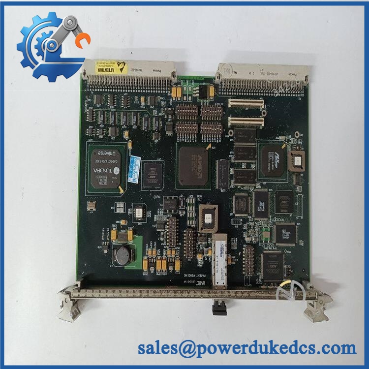
GE VMIVME-5565-110000
Module 6: Quality Assurance SOP
Incoming Identity Inspection
- Verify the GE / VMIC VMIVME-5565 product marking.
- Confirm and 332-015565-110000 identification.
- Check PCB revision, optical interface type, connector layout, and visible component population.
- Perform an OEM anti-counterfeit visual inspection against available GE Intelligent Platforms / VMIC documentation.
- Photograph the front panel, PCB, nameplate, connectors, and optical interfaces.
Mechanical Inspection
- Inspect all VME P1/P2 connector contacts for bent or recessed pins.
- Check the ejector handles and front-panel hardware.
- Inspect the optical transceiver area for contamination or mechanical damage.
- Verify there is no evidence of cracked solder joints, corrosion, overheating, or unapproved rework.
Power-On Verification
- Install the card in a known-good VME test chassis with suitable forced-air cooling.
- Apply controlled VME power and monitor startup current and board temperature.
- Perform the applicable power-on self-test (POST).
- Check ERR/RUN LEDs where those indications are provided by the host VME platform or test assembly; also record board status indications and startup diagnostics.
Reflective Memory Functional Test
- Verify VMEbus recognition of the node.
- Confirm local 128 MB reflective-memory access for the supplied configuration.
- Write controlled test patterns to local memory.
- Confirm that the same data appears at the corresponding address on a second known-good 5565 node.
- Repeat the test with different packet sizes to verify data movement across the network.
Communication Handshake Verification
- Establish an optical connection between the test node and a known-good reference node.
- Verify TX/RX link establishment and correct ring participation.
- Perform a controlled communication handshake verification.
- Test interrupt transfers where the fixture supports them.
- Check for network errors, FIFO faults, or missing-node indications.
Performance Verification
- Measure representative transfer rates against the documented 43 to 170 MB/s range, accounting for packet size and test conditions.
- Verify DMA operation where applicable.
- Confirm stable operation during repeated memory synchronization cycles.
- For multimode installations, verify the optical path at the intended cable length and connector type.
Final Shipment Record
- Record exact model, part number, board revision, memory configuration, and optical mode.
- Retain identification and functional-test photographs.
- Document test-node configuration and observed communication results.
- Package the board in ESD protection with connector and front-panel mechanical support.
Lifecycle note: Abaco Systems currently lists the VME-5565 as having entered Restricted Production Phase on July 17, 2026. For systems that must remain operational for several years, replacement-stock planning should therefore include the exact memory and optical configuration rather than relying only on the family number.











 Start Chat


