

Description
- HONEYWELL 261A1812P012 | Industrial Burner Protection Device
2. At-A-Glance Executive Brief
- Model: HONEYWELL 261A1812P012
- Part Type: Ultraviolet (UV) Flame Detector / Flame Scanner
- Application Family: Gas Turbine Combustion Safety System
- Core Function: Detects ultraviolet radiation generated by combustion flames and provides flame presence feedback to turbine or burner control systems.
- Key Specifications:
- UV flame detection technology.
- Used in GE-designed gas turbine generator applications.
- Fast flame response capability.
- Designed for industrial combustion monitoring.
- Supports safety interlock and burner management applications.
- Typical Procurement Category: Gas turbine spare, combustion monitoring component, flame scanner replacement.
3. Product Introduction
Inside a gas turbine combustion monitoring system, the HONEYWELL 261A1812P012 UV Flame Detector provides the critical feedback signal confirming whether combustion is present. A failed flame scanner can trigger false flame-out alarms, prevent turbine ignition, or cause unnecessary shutdown events. In field deployments, technicians normally inspect scanner alignment, cooling air supply, wiring condition, and signal quality before replacing the detector (optical contamination is a common cause of incorrect flame indication).
The 261A1812P012 is an OEM Honeywell flame detection component used in industrial turbine and burner protection applications. Documentation from industrial procurement references identifies this part number as a Honeywell flame detector / flame scanner installed in GE-designed gas turbine generator equipment. The device uses UV sensing principles to monitor combustion conditions and provide rapid flame status feedback to the control system.
4. Core Technical Specifications
| Parameter | Value |
|---|---|
| Manufacturer | Honeywell |
| Model Number | 261A1812P012 |
| Product Type | UV Flame Detector / Flame Scanner |
| Application | Gas turbine and burner flame monitoring |
| Detection Technology | Ultraviolet optical sensing |
| Operating Spectrum | Approx. 300–2500 nm |
| Response Time | Less than 0.5 seconds |
| Power Supply | 24 VDC |
| Current Consumption | Approx. 15 mA |
| Output Signal | SPDT relay contact |
| Maximum Relay Rating | Approx. 24 VDC / 0.2 A |
| Mounting Method | Wall or pipe mounting |
| Operating Temperature | Approx. -40°C to +70°C |
| Protection Requirement | Industrial combustion environment |
| Weight | Verify exact assembly revision |
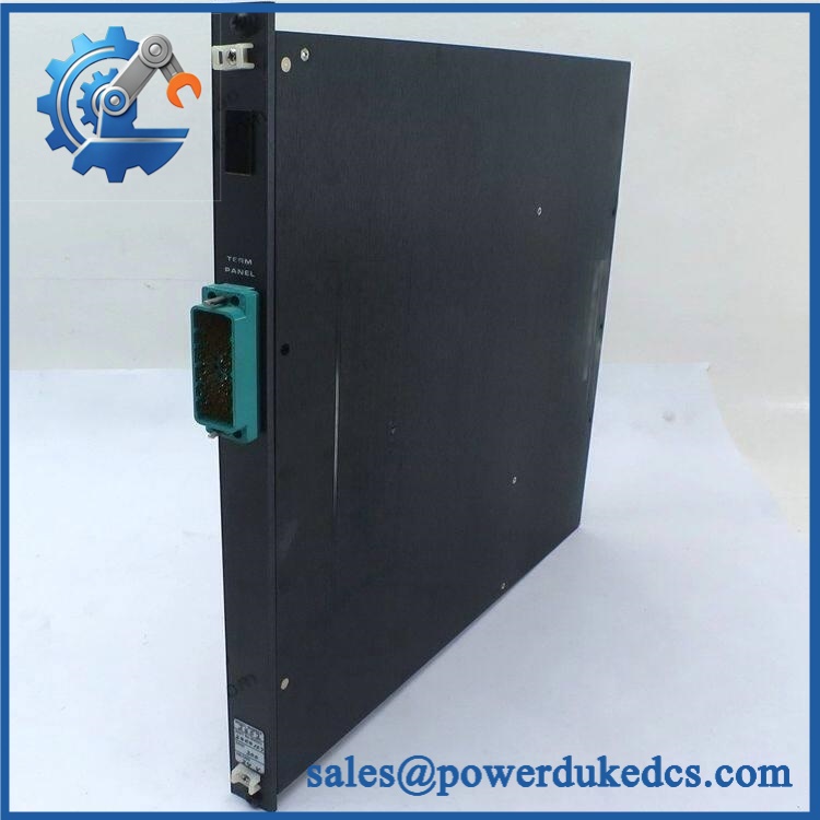
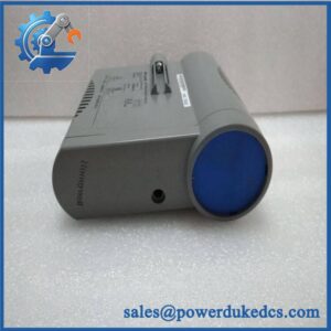
HONEYWELL 261A1812P012
5. Application Scenarios & Pain Points
At gas turbine power plants, the 261A1812P012 monitors combustion flame status where an incorrect signal can affect turbine startup or operation.
For industrial boilers and fired heaters, UV flame detection helps confirm burner ignition and continuous combustion conditions.
During turbine maintenance outages, keeping a tested flame scanner spare reduces restart delays caused by failed optical detection equipment.
Inside harsh combustion areas, the detector must maintain reliable sensing despite vibration, heat exposure, and contamination from combustion by-products.
Without a functioning flame detector, the protection system may interpret a healthy flame as a failure condition and initiate a shutdown sequence.
6. Common Error Codes & Diagnostic Symptoms
Symptom/Code: Flame Not Detected / False Flame Failure Alarm
→ Diagnosis: Possible dirty optical window, incorrect scanner alignment, weak UV signal, or detector failure.
→ Action: Clean and align the scanner; replace the 261A1812P012 if optical output remains abnormal.
Symptom/Code: Intermittent Flame Signal During Operation
→ Diagnosis: Possible loose wiring, vibration damage, unstable power supply, or aging UV sensing components.
→ Action: Inspect wiring and mounting condition, then replace the flame detector if required.
Symptom/Code: Ignition Sequence Abort
→ Diagnosis: Flame feedback is not confirmed within the required timing window.
→ Action: Verify burner conditions and scanner response; replace the unit if the detector fails testing.
7. Cross-Reference & Lifecycle Migration
- Related Identification:
- Honeywell P/N: 261A1812P012
- Referenced as a Honeywell flame detector installed in GE turbine applications.
- Replacement Considerations:
- Confirm exact part number.
- Verify mounting arrangement.
- Check electrical interface.
- Confirm turbine model compatibility.
- Verify flame scanner calibration requirements.
- Firmware Requirement:
The flame detector does not normally require firmware loading. Configuration is handled through the turbine control or burner management system. - Lifecycle Status: Legacy / Controlled Safety Spare.
- Maintain tested inventory for critical turbine systems.
- Store with turbine model, burner configuration, and replacement history.
8. Field Engineer’s Tech Notes (Anti-Pitfall Guide)
- Do not replace the flame scanner without checking optical alignment.
A misaligned detector can produce the same symptoms as a failed sensor. - Inspect the viewing path before installing a new unit.
Soot, deposits, or damaged sight tubes can block UV radiation and cause repeated flame faults. - Avoid touching optical surfaces during handling.
Contamination on the sensing window can reduce detection reliability.
9. Strict QA & Testing SOP
Step 1 — Incoming Inspection
- Verify Honeywell identification label.
- Confirm model number 261A1812P012.
- Record serial number and condition.
- Photograph optical window and housing.
Step 2 — Physical Examination
- Inspect mounting threads.
- Check electrical terminals.
- Verify housing condition.
- Inspect sensing window.
Step 3 — Electrical Testing
- Apply 24VDC supply.
- Verify current consumption.
- Check relay output operation.
Step 4 — Functional Testing
- Perform UV response test.
- Verify flame detection response.
- Confirm alarm output switching.
- Compare results with manufacturer specifications.
Step 5 — Packaging Control
- Protect optical surfaces.
- Use shock-resistant packaging.
- Include inspection documentation.
Test videos are available for verification procedures when required.
10. Buyer’s FAQ (Dynamic Q&A)
Q: Can the Honeywell 261A1812P012 be replaced while the turbine is operating?
A: No. Flame scanner replacement requires approved maintenance procedures and proper isolation of the combustion monitoring system.
Q: How can I confirm this is an original Honeywell 261A1812P012?
A: Verify the Honeywell label, complete part number, housing markings, optical assembly condition, serial information, and functional test records.
Q: Does this flame detector include turbine control software?
A: No. The detector provides flame feedback only. Turbine logic, alarms, and protective sequences remain inside the turbine control system.
Q: What should be confirmed before purchasing this spare?
A: Confirm turbine model, burner system configuration, mounting style, electrical interface, inspection status, and warranty conditions.
Procurement Note: The Honeywell 261A1812P012 should be managed as a critical combustion safety spare. Store the flame detector in clean protective packaging and maintain application records to support rapid turbine recovery after flame monitoring failures.




 Start Chat


