

Description
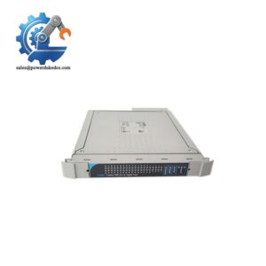
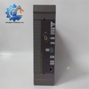
- ICS TRIPLEX T8402 | Factory Tested TMR Automation Module
2. At-A-Glance Executive Brief
- Model: T8402
- Brand: ICS TRIPLEX
- Series: Trusted® Safety Instrumented System (SIS)
- Part Type: Dual 24 VDC Digital Input Module
- Core Function: Interfaces field digital signals with the Trusted safety controller while providing diagnostic monitoring and fault detection.
- Key Specs:
- 60 digital input channels.
- 24 VDC field signal processing.
- Dual input architecture with 1oo2D diagnostic operation.
- Supports open-circuit and short-circuit field monitoring when configured with suitable field devices.
- Designed for safety-critical applications requiring high availability.
- Typical installation location: Trusted T8100/T8300 I/O chassis.
3. Product Introduction
Structure B — Technical Direct
Installed within the ICS TRIPLEX Trusted controller chassis, the T8402 operates as a dual-channel digital input interface between field devices and the safety processor. The module measures incoming 24 VDC signals, performs internal diagnostics, and reports validated input states to the Trusted system controller.
In field deployments, this module is commonly found in emergency shutdown (ESD), fire and gas detection, and critical process protection systems where input availability directly affects safety logic execution (—especially in plants where shutdown signals must remain available during a single hardware fault). The T8402 is not simply a signal converter; its diagnostic architecture is part of the safety loop design.
4. Core Technical Specifications
| Parameter | Value |
|---|---|
| Manufacturer | ICS TRIPLEX |
| Model | T8402 |
| Product Type | Dual 24 VDC Digital Input Module |
| System Family | Trusted® SIS |
| Input Channels | 60 channels |
| Input Voltage Range | 0–40 VDC measurement range |
| Nominal Field Voltage | 24 VDC |
| Input Architecture | Dual input with diagnostic monitoring |
| Input Measurement Method | Sigma-delta measurement circuits |
| Field Device Connection | Digital switches / sensors |
| Line Monitoring | Configurable open and short circuit detection |
| Backplane Supply Voltage | 20–32 VDC |
| Maximum Power Dissipation | Approx. 20 W |
| Sequence of Events Resolution | 1 ms |
| Communication Interface | Trusted internal chassis bus |
| Installation Position | Trusted I/O chassis slot |
| Operating Temperature | 0°C to +60°C |
| Storage Temperature | -25°C to +70°C |
| Relative Humidity | 10–95% non-condensing |
| Approximate Dimensions | 266 × 31 × 303 mm |
| Approximate Weight | 1.1–1.2 kg |
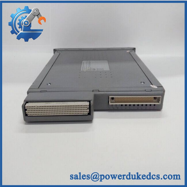
ICS TRIPLEX T8402
5. Application Scenarios & Pain Points
Bold technical conclusion:
The T8402 is used where ordinary PLC digital inputs are not sufficient. Safety systems require continuous diagnostics, fault reporting, and predictable behavior under abnormal conditions.
- Oil & Gas ESD Systems: Monitors emergency pushbuttons, pressure switches, and shutdown signals across critical process areas.
- Chemical Processing Plants: Handles safety interlock inputs where incorrect signal detection can lead to unsafe operating conditions.
- Power Generation Facilities: Interfaces turbine protection and auxiliary safety signals.
- Offshore Platforms: Supports distributed safety monitoring where vibration, temperature variation, and limited access increase maintenance difficulty.
- Refinery Fire & Gas Systems: Provides monitored input channels for detectors and safety devices.
In control rooms exposed to high cabinet temperatures above 50°C, inspect airflow, power supply loading, and rack ventilation. Heat-related failures may appear as intermittent channel diagnostics before complete module failure.
6. Common Error Codes & Diagnostic Symptoms
Symptom/Code: Input Channel Diagnostic Fault
→ Diagnosis: Internal channel measurement discrepancy, field wiring fault, or damaged input circuitry may prevent reliable signal validation.
→ Action: Check field wiring and termination assembly, then replace the T8402 if module diagnostics confirm hardware failure.
Symptom/Code: Module Health LED Fault / Chassis Diagnostic Alarm
→ Diagnosis: Internal self-test failure, backplane communication problem, or power supply issue may cause the module to enter fault state.
→ Action: Verify chassis power and slot connection before replacing the module.
Symptom/Code: Multiple Digital Inputs Lost Simultaneously
→ Diagnosis: Shared termination wiring, field supply failure, or module-level hardware problems may affect multiple channels.
→ Action: Test field supply and replace the input module if required.
7. Cross-Reference & Lifecycle Migration
- Compatible Platform: ICS TRIPLEX Trusted Safety System.
- Related Module Family:
- T8402 — Trusted Dual 24 VDC Digital Input Module.
- T8403 — Trusted TMR 24 VDC Digital Input Module (different architecture).
- Replacement Considerations:
- Confirm chassis slot compatibility.
- Verify termination assembly type.
- Restore original Trusted configuration after replacement.
- Firmware Requirement:
The module does not operate as an independent controller. Firmware compatibility must match the Trusted system processor and engineering configuration. - Lifecycle Status: Legacy / Limited Availability
For spare stock management, keep the original module configuration records, hardware revision, and system backup files. Safety system modules should not be installed without verifying the complete configuration baseline.
8. Field Engineer’s Tech Notes (Anti-Pitfall Guide)
- Do not replace the T8402 before checking field wiring.
A failed proximity switch, broken cable, or incorrect termination can generate the same diagnostic symptoms as a defective input module. - Protect the rear connector during handling.
The Trusted backplane interface contains critical contacts. Keep the module inside ESD shielding until installation and avoid touching connector surfaces.
9. Strict QA & Testing SOP
A professional inspection process for ICS TRIPLEX T8402 should include:
Step 1 — Incoming Inspection
- Verify model label: T8402.
- Record serial number and hardware revision.
- Inspect front panel indicators and chassis connector.
- Check for corrosion, cracks, or physical damage.
Step 2 — Electrical Verification
- Apply controlled 24 VDC input signals.
- Verify channel response.
- Check power consumption and diagnostic behavior.
Step 3 — Functional Testing
- Install in a compatible Trusted chassis.
- Verify module recognition.
- Test digital input transitions.
- Confirm diagnostic reporting.
Step 4 — Safety Configuration Review
- Compare module configuration.
- Verify channel assignment.
- Confirm engineering database compatibility.
Step 5 — Packaging Control
- Place module in anti-static ESD packaging.
- Add shock protection.
- Include inspection records.
Test videos, diagnostic screenshots, and inspection reports are available for verification.
10. Buyer’s FAQ (Dynamic Q&A)
Q1. Can the ICS TRIPLEX T8402 be hot-swapped?
A: The Trusted system supports replacement procedures designed for high availability, but the approved maintenance method must be followed. Confirm system design requirements before removing any safety I/O module.
Q2. “How do I verify this is a genuine T8402 module?”
A: Check the ICS TRIPLEX identification label, module revision, serial number, front-panel condition, and supplier testing documentation.
Q3. Does the T8402 include the latest firmware?
A: The module contains its own firmware, but compatibility depends on the Trusted controller version and system configuration. Verify revision compatibility before installation.
Q4. What warranty documentation should be requested?
A: Request functional test records, hardware condition details, serial traceability, and written warranty terms. For safety system spare modules, documented testing is a key purchasing requirement.



 Start Chat


