

Description
- Brand: MOTOROLA
- Full Model Number: 01-W3394F-03C
- System/Series Family: MVME2400 Series VME Processor Modules
- One-Sentence Core Function: Single-slot VME embedded processor board based on the Motorola MVME2432 platform
- Top 3 Hardcore Specs: 350 MHz MPC750; 64 MB ECC SDRAM; VMEbus P1/P2 interface with PMC carrier capability
- Stock Status: New Surplus / Fully Tested Refurbished — verify board revision, handle style, and installed configuration before shipment
Module 3: Technical Product Introduction
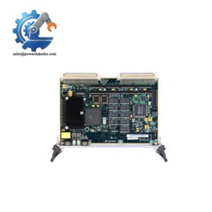
A failed CPU board in a legacy VME chassis can take an entire embedded control application offline while the surrounding I/O remains healthy. The MOTOROLA 01-W3394F-03C is cross-referenced in industrial equipment records with the MVME2432 VME processor platform. Motorola’s MVME2400 documentation identifies the MVME2432 family as a 350 MHz MPC750 processor board with 64 MB ECC SDRAM, designed as a VME controller and intelligent PMC carrier.
The board architecture is built around the VMEbus, with P1 and P2 connectors using 5-row 160-pin interfaces, while onboard circuitry provides bridges to the VMEbus and PCI-related resources. The MVME240x design occupies a single VME slot under its standard configuration and supports one or two PMC modules, depending on the installed arrangement. For the exact 01-W3394F-03C spare, confirm the physical board label and handle arrangement before assuming interchangeability with every MVME2432 variant.
Module 4: Application Scenarios & Field Realities
- Inside a legacy VME control chassis, the 01-W3394F-03C can serve as the embedded computing element coordinating VME I/O and application software. When a system fails to boot, check board seating, backplane contacts, memory integrity, and the boot environment before replacing downstream I/O cards. The MVME2400 platform is specifically documented as an embedded VME controller and intelligent PMC carrier.
- For systems using PMC expansion hardware, inspect the installed mezzanine arrangement before ordering a spare. The MVME240x architecture supports one or two PMC modules, and optional PCI expansion mezzanines can alter the physical configuration. A replacement board must accommodate the existing expansion hardware.
- During a shutdown replacement, preserve the original board configuration records. The MVME2432 family has multiple hardware variants, including versions with different rear-handle arrangements even though the core processor and memory specifications remain the same. The manual distinguishes MVME2432-1 and -3 by handle configuration.
- When troubleshooting intermittent VME faults, examine the P1/P2 connectors closely. The board draws its VMEbus power through these connectors and uses the same interface for VMEbus access, so poor contact can produce symptoms that resemble a CPU or application failure.
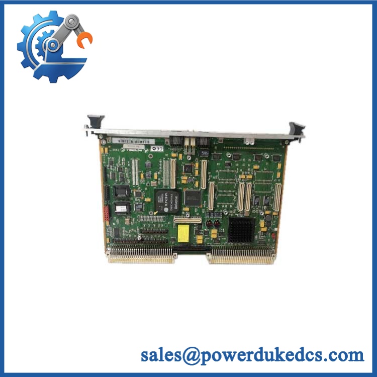
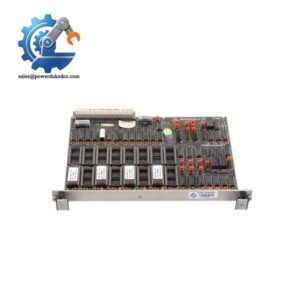
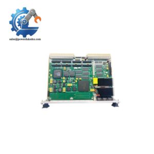
MOTOROLA 01-W3394F-03C
Module 5: Migration, Compatibility & Installation Traps
Replacement Matrix
| Replacement Type | Assessment |
|---|---|
| Drop-in Replacement | Conditional — appropriate when the chassis, exact configuration, memory, handle arrangement, PMC hardware, and software environment match |
| Software Compatible | Conditional — depends on the installed operating system, board support package, firmware, boot configuration, and application image |
| Hardware Modification Required | Normally no for an exact like-for-like 01-W3394F-03C replacement; verify P1/P2 interfaces, PMC hardware, and board mechanics first |
⚠️ Field Traps — Watch Out
1. Do not substitute every variant blindly.
Motorola documentation lists both and , each using a 350 MHz MPC750 and 64 MB ECC SDRAM, but with different handle configurations. Match the mechanical version to the existing chassis before installation.
2. Preserve the original boot environment.
A replacement processor board may pass a hardware POST while the application still fails because the firmware, boot parameters, operating system image, or application files do not match. Capture the existing configuration before removing the failed board.
3. Inspect the VME backplane before condemning the replacement board.
The MVME240x interfaces with the VMEbus through P1/P2 and receives its VMEbus power through those connectors. Bent contacts, contamination, or incomplete insertion can create apparent board faults.
4. Treat third-party electrical specifications cautiously.
One commercial listing incorrectly presents this reference with generic controller parameters such as 4–20 mA I/O and Modbus/Profibus support. Those values are not supported by the Motorola MVME2400 documentation and should not be copied into a technical PDP.
Module 6: Quality Assurance SOP
- OEM anti-counterfeit visual inspection — inspect Motorola identification, board labels, assembly markings, PCB revision, connectors, ejector hardware, and visible manufacturing details.
- Exact part-number verification — confirm 01-W3394F-03C character-for-character against the purchase order and physical board label.
- Model cross-reference verification — document the relationship between the exact board marking and the family only after the physical label has been checked. Current industrial records specifically cross-reference 01- with .
- Processor and memory verification — confirm the expected 350 MHz MPC750 architecture and 64 MB ECC SDRAM configuration for the family. Record discrepancies rather than assuming a visually similar board is equivalent.
- Mechanical inspection — inspect P1/P2 connectors, ejectors, board guides, PMC positions, front-panel hardware, and PCB surfaces for bent contacts, oxidation, cracks, or impact damage.
- Power-up self-test (POST) — energize the board only in a compatible VME test chassis. Record startup status, diagnostic indications, current behavior, and abnormal temperature rise.
- Memory diagnostic — execute a controlled ECC SDRAM test and record the result. Memory capacity alone does not prove memory integrity.
- VMEbus verification — confirm stable VMEbus access and verify that the board can communicate with the test backplane and required onboard resources.
- PMC interface verification — where a compatible PMC test card is available, confirm detection and operation of the installed PMC path. Do not install an unverified PMC simply to complete a test.
- Communication handshake verification — test only the interfaces actually present in the confirmed board configuration and application. Do not claim Modbus, Profibus, or Ethernet/IP compatibility without documentation for the specific installed configuration.
- Application-level validation — where the customer’s software image is available, boot the intended environment and verify expected VME I/O access and application operation.
- Final QC and packaging — document the exact part number, board revision, processor/memory configuration, diagnostic results, connector condition, ESD protection, and packaging status before shipment.
Engineering note: The strongest available evidence identifies with the Motorola VME processor family. Motorola’s technical documentation supports the key family specifications of 350 MHz MPC750, 64 MB ECC SDRAM, VMEbus P1/P2 interfaces, and PMC carrier capability. Because exists in more than one mechanical variant, the physical board configuration should be matched before approving it as a drop-in replacement.



 Start Chat


