

Description
- Brand: MOTOROLA
- Full Model Number: 01-W3394F-03F
- System/Series Family: ACE3600 / MOSCAD AP-4 communication platform
- Core Function: Communication interface module linking an RTU processor with serial and Ethernet communication networks
- Top 3 Hardcore Specs: Ethernet 10/100 Mbps; RS-232/RS-485 serial interfaces; 10.8–16 VDC backplane supply
- Stock Status: Verify current New Surplus, Factory Sealed, or Fully Tested Refurbished condition before order
Module 3: Technical Product Introduction
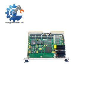
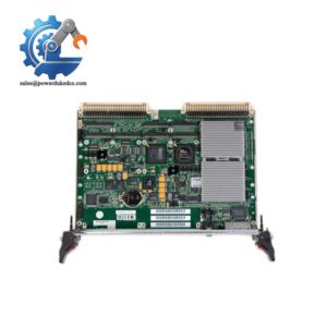
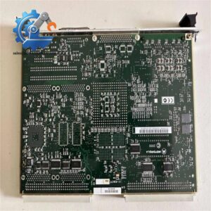
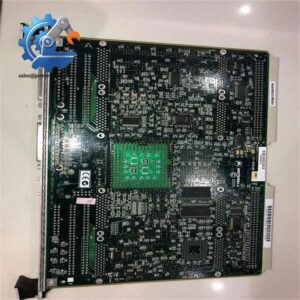
Communication failures in a remote RTU are often not caused by the field I/O at all. The gateway between the controller and its external networks can be the weak point. The MOTOROLA 01-W3394F-03F is identified in current technical listings as an AP-4 communication interface module for ACE3600 and MOSCAD RTU platforms, providing the communication path between the RTU processor and external wired or serial media. The module is also cross-referenced in equipment inventories as a Motorola communication-interface board associated with the ACE3600/MOSCAD family.
Published specifications for this exact part number list 10.8–16 VDC backplane power, 10/100 Mbps Ethernet, and RS-232/RS-485 serial interfaces, with protocol support reported for MDLC, Modbus RTU/TCP, DNP3, and TCP/IP. The same technical listing identifies the AP-4 platform as a multi-protocol communications interface rather than a simple serial converter. Because public documentation for the precise -03F revision is limited, the host-system manual and installed board markings should take precedence over third-party specifications during a replacement decision.
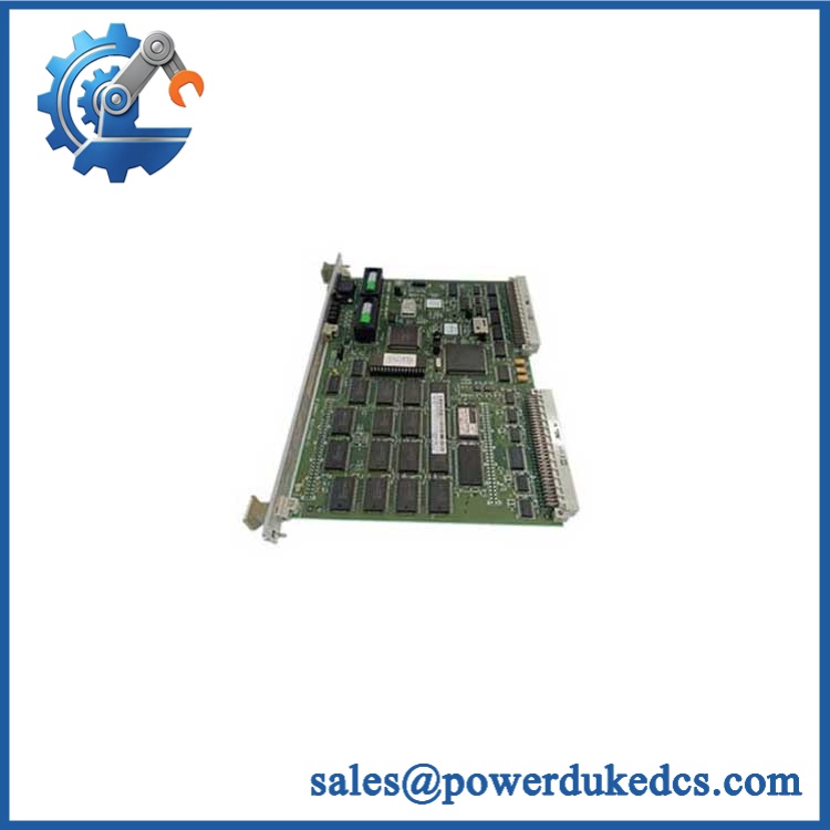
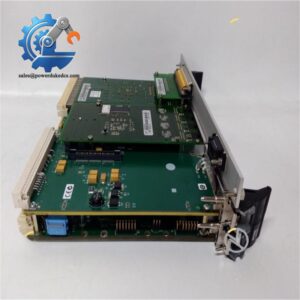
MOTOROLA 01-W3394F-03F
Module 4: Application Scenarios & Field Realities
- At remote water and pumping stations, an ACE3600 RTU may need to move tank levels, pump states, alarms, and control commands across different communications media. The AP-4 interface provides the network-facing path required to connect the RTU processor to Ethernet and serial communications.
- Within electrical-distribution telemetry, the combination of serial and Ethernet interfaces is useful when older field devices coexist with newer IP-based supervisory networks. The engineering issue is protocol configuration, not merely cable compatibility; confirm the installed MDLC, Modbus, DNP3, or TCP/IP configuration before swapping hardware.
- For oil and gas remote monitoring, an ACE3600/MOSCAD communication interface can sit between a field RTU and a higher-level SCADA environment. At a brownfield site, check the existing port assignment, baud rate, parity, station addressing, and network configuration before commissioning the replacement.
- During maintenance on legacy Motorola RTU cabinets, the full board identification should be recorded before removal. The requested 01-W3394F-03F also appears in the same product family as other C73249 and 01-W3394F assemblies, but those related numbers should not be treated as interchangeable without a hardware and configuration comparison.
Module 5: Migration, Compatibility & Installation Traps
Replacement Matrix
Exact 01-W3394F-03F with matching ACE3600/MOSCAD host configuration: Drop-in Replacement
When the board revision, chassis, slot assignment, firmware requirements, communication ports, and application configuration match the installed unit, replacement can normally be handled as a direct hardware exchange.
Same 01-W3394F family with different suffix or revision: Software Compatible / Hardware Verification Required
The common base number is not sufficient evidence of equivalence. Compare revision markings, port configuration, firmware compatibility, memory configuration, and host-system documentation before installation.
Different /MOSCAD communication module: Hardware Modification Required unless explicitly approved
A module with similar Ethernet or serial functions may still use different backplane interfaces, firmware, protocol support, or slot requirements.
⚠️ Field Traps (Watch Out)
Voltage verification: Published data for the 01–03F identifies a 10.8–16 VDC backplane supply. Do not apply a generic 24 VDC industrial supply directly to the module unless the host chassis documentation explicitly supports it.
Protocol and port mismatch: Having an RJ45 or serial connector does not guarantee identical network behavior. Before migration, record the existing Ethernet parameters, serial settings, protocol assignments, and station addressing. A hardware swap can appear successful at power-up while the RTU remains unable to communicate with the SCADA master.
Variant confusion: Commercial listings associate the 01- family with several different assemblies and revisions. The -03F marking should be matched exactly against the original board label and host-system bill of materials.
Module 6: Quality Assurance SOP
Pre-Shipment QA Protocol for MOTOROLA 01–03F
- Step 1 — Identity Verification: Confirm the complete 01–03F marking, board revision, serial or manufacturing information where available, and host-platform identification.
- Step 2 — OEM Anti-Counterfeit Visual Inspection: Inspect Motorola labeling, PCB revision marks, component references, connector bodies, board finish, mounting hardware, and evidence of unauthorized rework.
- Step 3 — Mechanical Inspection: Check the PCB edge connector, Ethernet and serial interfaces, mounting points, locking hardware, and housing or carrier assembly for damage.
- Step 4 — Power Verification: Confirm the intended backplane supply from the host equipment documentation and verify the test source is within the published 10.8–16 VDC range before energization.
- Step 5 — Power-On Self-Test: Install in a controlled compatible chassis and verify normal startup, status indications, board recognition, and absence of hardware diagnostics.
- Step 6 — Ethernet Test: Establish a controlled 10/100 Mbps network connection and verify link status, packet exchange, and expected module recognition by the host system.
- Step 7 — Serial Interface Test: Test the applicable RS-232 and RS-485 interfaces with approved loopback or protocol-test equipment, checking signal integrity and configured parameters.
- Step 8 — Protocol Handshake Verification: Where the laboratory setup permits, verify the expected MDLC, Modbus, DNP3, or TCP/IP communication path used by the target installation.
- Step 9 — Stability Test: Operate the module under representative communications traffic and monitor for intermittent resets, link drops, unexpected error indications, or abnormal thermal behavior.
- Step 10 — Final QC Record: Record model, revision, host platform, measured supply voltage, Ethernet result, serial-port result, protocol test result, visual condition, test date, and final QC disposition.
Technical Verification Note: Current public evidence identifies MOTORO as an AP-4 communication interface module for /MOSCAD RTU systems, with published specifications including 10.8–16 VDC backplane power, 10/100 Mbps Ethernet, RS-232/RS-485 serial interfaces, and multi-protocol support. Because exact -03F primary-source documentation is limited in the public record, the physical board label and the installed Motorola system documentation should be treated as the final authority for replacement and commissioning.



 Start Chat


