

Description
- Brand: Motorola / Emerson
- Full Model Number: MVME51005E-0163
- System/Series Family: MVME5100 Series VMEbus Single Board Computers
- One-Sentence Core Function: 6U VMEbus PowerPC single-board computer providing CPU, memory, PCI, Ethernet, serial, and PMC expansion functions
- Top 3 Hardcore Specs: 450 MHz MPC750; 512 MB ECC SDRAM; 17 MB Flash + 1 MB L2 cache
- Stock Status: Stock condition, revision, and included PMC/IPMC accessories to be confirmed
Module 3: Technical Product Introduction
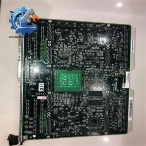
When a legacy VME control computer fails, the challenge is rarely the processor board alone. The replacement must match the VMEbus architecture, front-panel standard, memory population, boot environment, and any installed PMC or IPMC hardware. Motorola MVME51005E-0163 is the extended-temperature version of the MVME5100 single-board computer, configured with a 450 MHz MPC750 PowerPC processor, 512 MB ECC SDRAM, 17 MB Flash memory, 1 MB L2 cache, and an IEEE 1101-compatible front panel. The board interfaces with the VMEbus through its P1 and P2 connectors and supports two PMC expansion positions.
The MVME5100 architecture combines the PowerPC processor with the Hawk PCI/host-bridge and memory-controller ASIC and the Universe VME interface. The platform provides dual 10Base-T/100Base-TX Ethernet, two 16550-compatible asynchronous serial interfaces, and dual 32/64-bit PMC expansion slots. Motorola documentation specifies a 100 MHz front-side bus and up to 17 MB of Flash across the platform family. For the -0163 configuration specifically, supplier technical records consistently identify 512 MB ECC SDRAM and 17 MB Flash, with the IEEE front-panel arrangement distinguishing it from the -0161 Scanbe version.
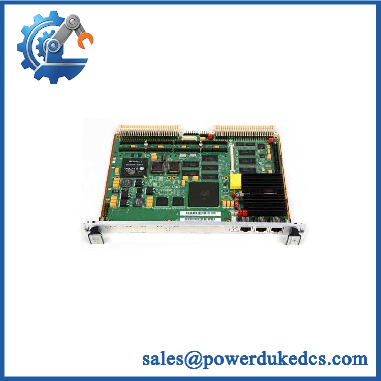
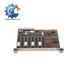
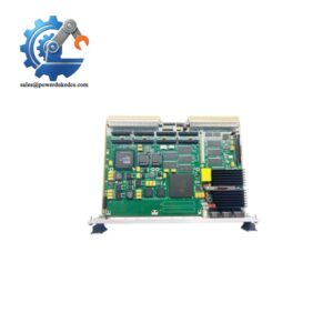
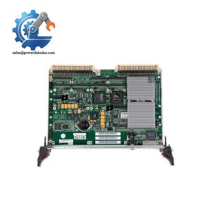
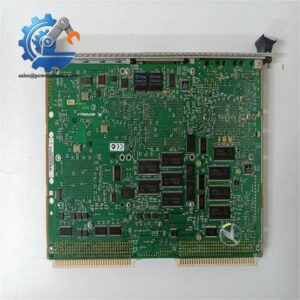
Motorola MVME51005E-0163 |
Module 4: Application Scenarios & Field Realities
- Inside legacy VME-based control cabinets, the MVME51005E-0163 acts as the embedded host rather than a conventional PLC CPU. Confirm the existing VME chassis, P1/P2 backplane connections, and system slot assignment before installing the board; the processor module depends on the VMEbus backplane for power and external bus communication.
- For systems using PMC expansion, check both mezzanine positions and the associated rear-I/O architecture before ordering a replacement. The MVME5100 supports two IEEE P1386.1-compatible PMC slots, while certain SBC/IPMC configurations also use additional transition hardware. A replacement board without the required PMC or IPMC accessories may boot correctly and still fail to provide the original machine interface.
- Where an extended-temperature board is required, the 5E designation should be preserved. Commercial and technical references distinguish the MVME51005E-0163 from the standard MVME5100-0163, while the -0163 suffix identifies the IEEE 1101 front-panel implementation. Do not substitute an apparently similar -0161 board without checking the mechanical front-panel requirement.
- During field recovery of an older embedded application, preserve the PPCBoot/PPCBug configuration and boot media before removing the failed board. The MVME5100 uses PPCBug firmware and provides configurable boot parameters, so restoring the hardware without documenting the original boot configuration can turn a board replacement into a software commissioning issue.
Module 5: Migration, Compatibility & Installation Traps
Replacement Matrix
Replacement Classification: Drop-in Hardware Replacement Within the Matching Configuration
A like-for-like MVME51005E-0163 replacement is generally a direct board exchange when the installed system already uses the same extended-temperature variant, processor configuration, memory population, front-panel standard, and PMC/IPMC arrangement. Motorola’s documentation covers the family including the -0163 configuration, and supplier records identify the exact -0163 variant as a 450 MHz MPC750 board with 512 MB ECC SDRAM and 17 MB Flash.
MVME51005E-0163 → -0163: Treat this as a configuration-dependent substitution rather than assuming complete equivalence. Both use the -0163 architecture, but the 5E designation is associated with the extended-temperature version. Environmental requirements must therefore be checked before replacing a 5E board with a standard-temperature unit.
→ -0161: Not a direct mechanical substitution when the cabinet requires the IEEE 1101 front-panel arrangement. The -0161 version uses the Scanbe front-panel configuration, while -0163 uses IEEE-style hardware.
⚠️ Field Traps — Watch Out
1. Front-panel mismatch: The -0163 configuration is tied to the IEEE front-panel arrangement. A board with the same processor and memory but a Scanbe front panel can create a mechanical interference problem in the chassis even though the electronics are closely related. Verify the front-panel standard before installation.
2. Backplane dependency: requires its main-board connection to both P1 and P2 for normal VMEbus operation. Inspect the backplane connectors and seating depth carefully; a partially seated board can produce symptoms that resemble a CPU or memory failure.
3. Boot and firmware configuration: Do not assume a replacement board will inherit the original application’s boot behavior automatically. Document PPCBug parameters, boot-device selection, network settings, and any installed firmware version before removing the original module.
Module 6: Quality Assurance SOP
The should be treated as a complete embedded-computing board during pre-shipment inspection.
- OEM identification visual inspection: Verify Motorola/Emerson markings, part number, board identification labels, serial number, revision, front-panel markings, and major component references.
- Processor verification: Confirm the installed processor family and identify the 450 MHz MPC750 configuration expected for the -0163 variant.
- Memory verification: Confirm the installed 512 MB ECC SDRAM population and inspect memory devices and sockets/mezzanine interfaces for contamination or physical damage.
- Flash verification: Verify the expected 17 MB Flash configuration and record the installed boot/firmware revision where accessible.
- Mechanical inspection: Examine P1/P2 VME connectors, PMC connectors, front-panel handles, heatsink, board guides, mounting points, and rear-I/O interfaces.
- Power-on self-test (POST): Install the board in an approved VME test chassis and verify CPU, memory, bus, and diagnostic startup behavior without applying production-system loads.
- PPCBug verification: Confirm that the board reaches the expected firmware/debugger environment and record diagnostic output, memory detection, and board identification.
- VMEbus verification: Test master/slave access through the VME interface using an approved diagnostic application and confirm expected address/data transfers.
- Ethernet verification: Test both 10/100 Ethernet channels and confirm stable link negotiation and packet transfer.
- Serial-port verification: Test both 16550-compatible asynchronous ports with loopback or an approved serial diagnostic fixture.
- PMC interface verification: Where the board is supplied with PMC hardware, verify correct enumeration and data transfer through the installed expansion device.
- Thermal observation: Monitor processor and board temperature during an extended functional run. For the 5E extended-temperature version, confirm thermal behavior under the intended test conditions rather than assuming environmental qualification from appearance.
- Final QC record: Retain part-number photographs, processor and memory identification, firmware/PPCBug revision, VMEbus test results, Ethernet and serial results, PMC test results where applicable, and final QC approval.
The is a VMEbus embedded computer, not a conventional PLC I/O module. Its critical replacement attributes include the 450 MHz MPC750 processor, 512 MB ECC SDRAM, 17 MB Flash, 1 MB L2 cache, IEEE 1101 front panel, VME P1/P2 interface, and the required PMC/IPMC configuration. Those details should be matched before a warehouse spare is released for a production VME chassis.



 Start Chat


