

Description
- Brand: TRICONEX
- Full Model Number: 3201S2
- System/Series Family: Triconex General Purpose Tri-GP system
- Core Function: Enhanced Communication Module providing controller access, Ethernet and serial communications, diagnostics, and network protocol services
- Top 3 Hardcore Specs: 2 Ethernet network ports; 3 serial ports; 24 VDC nominal supply
- Stock Status: Verify current New Surplus, Factory Sealed, or Fully Tested Refurbished condition before order
Module 3: Technical Product Introduction
When a Tri-GP controller must communicate with a workstation, DCS, remote equipment, or another controller, the communication module becomes the central interface point. TRICONEX 3201S2 is the enhanced Communication Module (CM) for Tri-GP systems. Schneider Electric documentation lists Model 3201S2 as the Tri-GP enhanced CM and specifies support for network and serial communications, including TriStation, TSAA, peer-to-peer services, Modbus, GPS time synchronization, Triconex time synchronization, and related network functions. A single Tri-GP controller can support up to two CMs on one CM baseplate.
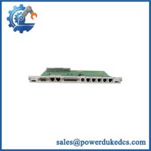
The interface density is the important field specification. The 3201S2 provides two Ethernet network ports and three serial ports, allowing independent communications paths within the same controller. Schneider’s Tri-GP planning documentation identifies a 24 VDC nominal supply, with a specified operating range of 19.2 to 30 VDC and maximum power interruption time of 1 ms.The communication architecture can support Modbus slave operation over the serial ports, Modbus master over network ports, plus Triconex-specific communication and time-synchronization services.
Module 4: Application Scenarios & Field Realities
- At a Tri-GP engineering workstation connection, the 3201S2 provides the communication path used to connect the Tri-GP controller with the TriStation workstation. Schneider specifically recommends establishing a serial connection first during initial setup because it is less complex during commissioning; network communication can then be configured for normal operation.
- For legacy DCS integration, the three serial interfaces and two Ethernet ports allow different communication channels to coexist. Modbus RTU can be configured over serial ports, while Modbus TCP and other Ethernet services can be used where supported by the project configuration. Protocol selection must be checked against the actual Tri-GP application rather than inferred from the connector type.
- Where redundant communications are required, one Tri-GP controller can accommodate up to two communication modules on a single CM baseplate. This permits separate communication paths or additional independent ports, depending on the system design.
- During brownfield maintenance, the module should be treated as a configured communications asset. IP addresses, serial parameters, protocol assignments, station addressing, and time-synchronization settings must be captured before removal. A replacement can show normal front-panel operation while still failing to communicate because one of these parameters was not restored.
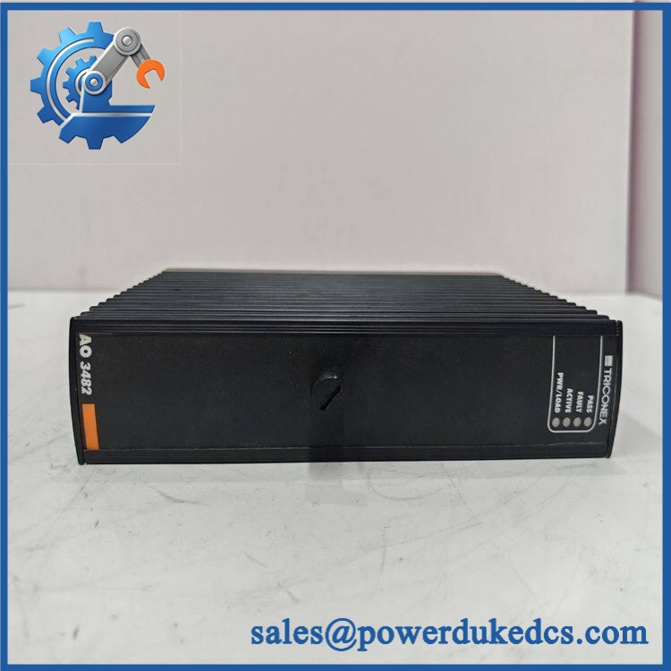
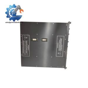
TRICONEX 3201S2
Module 5: Migration, Compatibility & Installation Traps
Replacement Matrix
Exact 3201S2 with matching Tri-GP configuration: Drop-in Replacement
When the replacement has the same hardware type, approved firmware level, CM baseplate arrangement, port usage, and project configuration, it can generally be exchanged without changing the application logic.
3201S2 firmware or configuration revision change: Software Compatible / Configuration Verification Required
The communications module may require restoration of network addresses, serial settings, protocol assignments, or other project parameters after replacement. Verify the installed firmware and TriStation project before release.
3201 or another Triconex CM substituted for 3201S2: Hardware Verification Required
The standard Trident CM Model 3201 and the Tri-GP enhanced CM Model 3201S2 are related but belong to different system configurations. Technical documentation explicitly distinguishes the enhanced 3201S2 for Tri-GP systems.
⚠️ Field Traps (Watch Out)
Protocol-configuration trap: The 3201S2 supports multiple communication protocols, but availability differs by port. Schneider’s protocol matrix shows, for example, Modbus slave on serial ports and Modbus master functions on the network interfaces. Do not move a configured service from one port to another without checking the approved project configuration.
Addressing trap: A hardware replacement does not guarantee automatic restoration of the previous network identity. Record Ethernet addressing, serial port parameters, controller node information, and communication assignments before removing the original module.
Supply-voltage trap: The Tri-GP planning data specifies 24 VDC nominal, with an operating range of 19.2–30 VDC. Verify the controller’s actual power feed and grounding arrangement before testing a replacement.
Module 6: Quality Assurance SOP
Pre-Shipment QA Protocol for TRICONEX 3201S2
- Step 1 — Identity Verification: Confirm TRICONEX marking, 3201S2 model number, serial information, hardware revision, firmware revision, and any available production-code data.
- Step 2 — OEM Anti-Counterfeit Visual Inspection: Inspect the front label, barcode, PCB markings where accessible, connector bodies, retaining hardware, LEDs, and enclosure finish for inconsistencies or evidence of unauthorized modification.
- Step 3 — Mechanical Inspection: Check the CM housing, baseplate connector, Ethernet interfaces, serial connectors, locking mechanism, and mounting hardware for deformation, contamination, corrosion, or damaged contacts.
- Step 4 — Supply Verification: Confirm the test fixture provides the specified 24 VDC nominal input and remains within the documented 19.2–30 VDC operating range.
- Step 5 — Power-On Self-Test: Install the module in an approved Tri-GP test configuration and verify normal startup, PASS/FAULT indication, controller recognition, and absence of module diagnostics.
- Step 6 — Ethernet Port Test: Test both network ports individually for link establishment, packet exchange, and expected controller communication behavior.
- Step 7 — Serial Interface Test: Exercise all three serial ports with approved loopback or protocol-test equipment. Verify signal integrity, configured baud rate, parity, stop bits, and port assignment.
- Step 8 — Communication Handshake Verification: Establish a controlled connection using the intended TriStation, Modbus, or Triconex communication service and verify successful data exchange.
- Step 9 — Time-Synchronization and Stability Test: Where applicable, verify the configured time-synchronization service and operate the module under representative communication traffic to identify intermittent resets or port dropouts.
- Step 10 — Final QC Record: Record model, serial number, firmware/hardware revision, measured supply voltage, Ethernet test results, all three serial-port results, communication-protocol test results, visual condition, test date, and final QC disposition.
Technical Verification Note: Schneider Electric documentation identifies 3201S2 as the enhanced Tri-GP Communication Module. The Tri-GP configuration guide lists two network ports and three serial ports and documents support for TriStation, TSAA, peer-to-peer communication, Modbus, GPS synchronization, Triconex time synchronization, and other services. The Tri-GP planning documentation specifies 24 VDC nominal input with a 19.2–30 VDC operating range.



 Start Chat


