

Description
- Brand: TRICONEX
- Full Model Number: 3415
- System/Series Family: Tricon safety instrumented systems
- One-Sentence Core Function: Safety digital output module for driving field actuators and shutdown devices from the Tricon control system
- Top 3 Hardcore Specs: Digital output function; TMR safety architecture; exact voltage/channel configuration to be verified from module revision
- Stock Status: Exact hardware revision and electrical configuration to be confirmed
Module 3: Technical Product Introduction
When a shutdown valve, solenoid, relay, or other final element stops responding, the output interface deserves inspection before the main controller is blamed. TRICONEX 3415 is identified by current industrial references as a safety digital output module used to convert Tricon control decisions into discrete field commands. The module is associated with the Tricon safety architecture and is intended for high-integrity output control applications such as emergency shutdown and protective interlocks.
There is an important procurement limitation with this model. The current public Tricon product guide retrieved for verification lists several standard digital-output families—such as 3601E/3601T, 3603E/3603T, 3604E, 3607E, 3611E, 3617E, 3623/3623T, 3624, 3625, 3664, and 3674—but does not list Model 3415 in that standard-model table. Current reseller references nevertheless identify 3415 as a safety digital-output product. Because the manufacturer-level electrical specification for this exact 3415 reference could not be independently confirmed, voltage, channel count, current rating, isolation, and response-time figures should be verified from the physical nameplate and applicable Tricon documentation before purchase or installation.
Module 4: Application Scenarios & Field Realities
- On emergency shutdown circuits, a digital-output failure can prevent the expected command from reaching a solenoid or shutdown relay. For a 3415 replacement, verify the complete downstream circuit—including interposing relays, fuses, field power, and actuator coil—before declaring the output module defective.
- For turbine or compressor protection, digital outputs may be associated with trip commands where timing and fail-state behavior are critical. The replacement procedure should therefore preserve the existing logic configuration and validate the final output state under the approved maintenance test rather than relying on a simple LED check.
- In process-unit interlock systems, output compatibility depends on the actual load characteristics. A relay coil or solenoid can have a substantially different inrush requirement from its steady-state current, so the installed field load should be compared with the certified output specification for the exact 3415 revision.
- During legacy Tricon maintenance, model-number verification is particularly important. Current Tricon documentation confirms that Tricon chassis slots are mechanically keyed for specific module types, while the standard product guide does not show 3415 in its published standard I/O model table. Confirm the module keying, baseplate, and controller generation before inserting a warehouse spare.
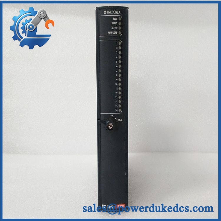
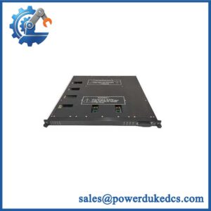
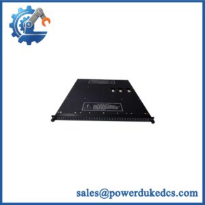
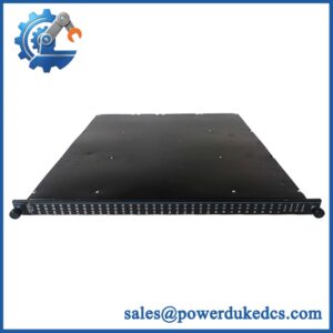
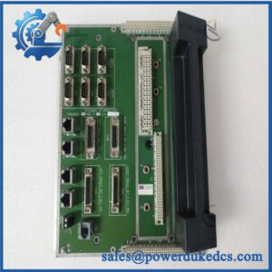
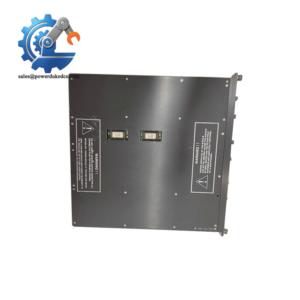
TRICONEX 3415
Module 5: Migration, Compatibility & Installation Traps
Replacement Matrix
Replacement Classification: Configuration-Matched Replacement — OEM Revision Verification Required
A TRICONEX 3415 should be treated as a direct replacement only when the exact installed controller architecture, module revision, baseplate, field termination, and output electrical characteristics have been confirmed. Current supplier sources classify 3415 as a safety digital-output module, but the retrieved manufacturer-level Tricon product guide does not provide a standard-model specification for this number.
3415 → standard Tricon digital-output modules such as 3601E or 3604E: Hardware Modification Required. The Tricon product guide identifies these as separate, explicitly specified output families with different voltage and isolation configurations. A substitute should not be selected from the general category “digital output.”
⚠️ Field Traps — Watch Out
1. Unverified electrical rating: Do not assume that “3415” means 24 VDC, a specific channel count, or a particular current capacity based only on third-party listings. The exact field rating must come from the installed revision’s documentation or nameplate.
2. Baseplate and mechanical keying: Tricon chassis slots are mechanically keyed to module types. A replacement that is electrically similar but intended for another slot family should not be forced into the chassis. Confirm the physical keying and approved baseplate before energization.
3. Field-load behavior: Verify the complete actuator circuit, including coil resistance, inrush current, suppression devices, external power, and interposing relays. A nominally correct output voltage does not prove that the connected load is compatible.
Module 6: Quality Assurance SOP
Because the exact 3415 electrical specification could not be independently confirmed from the retrieved manufacturer-level documentation, QA should begin with identity verification and only then proceed to functional testing.
- OEM identification visual inspection: Verify TRICONEX markings, 3415 model number, serial number, hardware revision, front-panel labeling, connector layout, and mechanical keying.
- Documentation reconciliation: Compare the nameplate and revision against the customer’s Tricon project documentation and the applicable OEM manual before applying power.
- Mechanical inspection: Examine the PCB, connector interface, ejector hardware, keying features, LEDs, mounting points, and exposed components for corrosion, contamination, impact, or repair evidence.
- Baseplate verification: Install the unit only in the approved Tricon test chassis and matching termination arrangement.
- Power-on self-test (POST): Confirm the expected startup indication, diagnostic state, PASS/FAULT behavior, and controller recognition.
- Output-channel test: Exercise every documented output using a controlled resistive or approved representative load. Record the commanded state and actual electrical response.
- Load test: Where the exact certified current rating is available, test representative loads below the rated limit and verify stable switching under both steady-state and approved transient conditions.
- Isolation test: Perform the manufacturer-approved isolation verification where applicable, protecting sensitive circuitry from inappropriate test voltages.
- Fault-response verification: Test the module’s documented diagnostic and safe-state response using the authorized Tricon maintenance procedure.
- TMR verification: Confirm correct participation in the Tricon voting and diagnostic architecture under the approved test configuration.
- Extended stability test: Operate the module under representative output activity while monitoring status indicators, field-load behavior, controller diagnostics, and temperature.
- Final QC record: Retain complete part-number photographs, hardware revision, documentation cross-check, output test results, diagnostic results, thermal observations, and final QC approval.
For TRICONEX 3415, exact identification should take priority over generic catalog specifications. Current industrial references classify it as a safety digital-output module, while the retrieved Tricon product guide lists other standard output families but does not include 3415 in its standard-model table. For a production spare, verify the physical unit’s complete marking and applicable OEM documentation before publishing fixed channel-count, voltage, current, or environmental specifications.



 Start Chat


