

Description
- Brand: Triconex / Invensys
- Full Model Number: 3501E
- System/Series Family: Tricon v9–v11
- Core Function: 32-point non-commoned, individually isolated 115 VAC/VDC TMR digital input acquisition
- Top 3 Hardcore Specs: 32 isolated input points; 90–155 VAC/VDC recommended range; 47–63 Hz AC or DC operation
- Maximum Input Voltage: 155 VAC/VDC
- Switching Threshold: 69 VAC/VDC typical Off-to-On; 36 VAC/VDC typical On-to-Off
- Input Impedance: >8.5 kΩ nominal
- Input Delay: <8 ms Off-to-On; <15 ms On-to-Off
- Point Isolation: 1,000 VAC minimum / 1,500 VDC minimum
- Status Indicators: 32 point LEDs; PASS, FAULT, ACTIVE
- Logic Power: <10 W
- Field Power Load: 1.5 W per On point; 2.9 W at maximum field voltage
- Stock Status: New Surplus or Fully Tested Refurbished; exact revision to be confirmed
Module 3: Technical Product Introduction
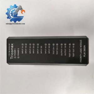
A 115 VAC status circuit cannot be evaluated like a 24 VDC digital input. The TRICONEX 3501E is a 32-point TMR digital input module intended for 115 VAC/VDC field signals, with each point individually isolated and non-commoned. The three independent input circuits process the field signal separately, supporting the Tricon fault-tolerant architecture. Tricon technical documentation identifies the 3501E as part of the Tricon digital-input family for v9–v11 systems.
For commissioning work, the threshold and timing figures are more useful than the nominal “115 V” label alone. The recommended input range is 90–155 VAC/VDC, with 155 VAC/VDC maximum. Off-to-On switching occurs at approximately 69 V typical, with 86 V worst-case, while On-to-Off occurs at approximately 36 V typical, with 28 V worst-case. Input impedance is greater than 8.5 kΩ, with response times below 8 ms for Off-to-On and below 15 ms for On-to-Off. The 3501E provides at least 1,000 VAC / 1,500 VDC point isolation.
Module 4: Application Scenarios & Field Realities
- For 115 VAC equipment-status circuits, 3501E can monitor breaker status, motor contactor feedback, valve-position switches, permissive signals, and other discrete field conditions where a lower-voltage DC input module would be electrically unsuitable. The 32-point architecture keeps each field point isolated rather than tying the inputs into common groups.
- Inside a Tricon shutdown or process-protection cabinet, the three-channel input structure allows the controller to acquire and compare the same field information through independent electronic paths. A replacement therefore needs more than a simple LED and continuity check; all TMR input paths should be evaluated.
- Where the field signal is derived from an AC relay contact, the 47–63 Hz operating range is relevant during loop testing. A signal that measures correctly on a DC meter can still behave differently under switching or waveform conditions, so the actual field source should be represented during bench qualification.
- During troubleshooting of a marginal field circuit, pay particular attention to the hysteresis between the Off and On thresholds. A slowly decaying 115 VAC signal can pass through the transition region rather than producing a clean state change. The published typical hysteresis is approximately 32 VAC.
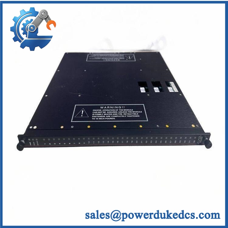
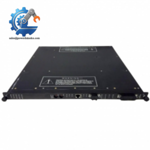
TRICONEX 3501E
Module 5: Migration, Compatibility & Installation Traps
Replacement Matrix
Replacement classification: Drop-in Replacement when the installed Tricon chassis uses the same 3501E configuration, compatible termination assembly, field-power arrangement, and system revision.
Software compatibility: Configuration verification required. The 3501E is an I/O module rather than a programmable processor, but channel assignments, diagnostics, alarm handling, and application logic still need to match the existing Tricon configuration.
Cross-model replacement: Hardware and application verification required. The Tricon family includes other 32-point digital-input modules for 48 VAC/VDC, 24 VAC/DC, and low-threshold 24 VDC signals. Those variants have different operating ranges and electrical characteristics and should not be substituted based on point count alone.
Field Traps — Watch Out
1. Do not substitute a 24 VDC input module. The 3501E is designed around a 90–155 VAC/VDC recommended range. A 24 VDC digital-input module may physically belong to the same general product family while being completely unsuitable for the installed field voltage.
2. Verify the field voltage at the module terminals. A nominal 115 VAC source can fall substantially under load because of aging contacts, long wiring, fuse resistance, or a failing relay. A signal below the specified On threshold can produce an intermittent or ambiguous state instead of a clean input.
3. Respect the isolation rating. Each 3501E input is individually optically isolated. Do not defeat that architecture by combining field returns or altering the termination arrangement without reviewing the approved Tricon wiring design. The documented minimum point isolation is 1,000 VAC / 1,500 VDC.
4. Do not confuse 3501E with 3501T. Both modules accept 115 VAC/VDC inputs and share the same general 32-point TMR architecture, but 3501T has a higher point-isolation minimum. If the installed system requires the higher-isolation version, 3501E is not an automatic substitute.
Module 6: Quality Assurance SOP
Pre-Shipment Inspection Protocol for TRICONEX 3501E
- OEM identity inspection: Verify Triconex/Invensys markings, exact 3501E designation, hardware revision, serial number, front-panel labeling, and additional assembly identifiers.
- Variant verification: Confirm that the module is 3501E, not 3501T, 3502E, 3503E, or another Tricon digital-input variant.
- Mechanical inspection: Examine the enclosure, module guides, card-edge/backplane interface, status LEDs, mounting features, and accessible PCB surfaces for corrosion, contamination, deformation, cracked components, or unauthorized repair.
- Connector inspection: Check all module and field interfaces for oxidation, bent contacts, damaged housings, loose hardware, or foreign material.
- Power-on self-test: Install the module in a compatible Tricon test chassis and verify startup behavior, including PASS, FAULT, and ACTIVE indications.
- 32-channel verification: Exercise every input point independently; do not qualify a 32-point module from a single representative channel.
- AC input test: Apply calibrated 115 VAC test signals within the documented operating range and verify correct state recognition on all channels.
- DC input test: Where the test procedure permits, apply representative DC levels and verify correct operation across the specified 90–155 VDC range.
- Threshold verification: Test representative voltage levels around the documented Off-to-On and On-to-Off thresholds, including the transition region, and record the measured switching behavior.
- Timing verification: Apply controlled transitions and verify response within the documented <8 ms Off-to-On and <15 ms On-to-Off limits.
- Isolation verification: Perform an approved controlled isolation test against the applicable 1,000 VAC / 1,500 VDC minimum point-isolation requirement.
- Diagnostic verification: Check the module’s PASS, FAULT, ACTIVE, and individual point indications under normal operation and controlled fault conditions.
- TMR path verification: Where the test environment permits, validate all three input paths and confirm correct communication with the Tricon I/O architecture.
- Field-power load test: Apply representative channel loading and monitor current draw and thermal behavior; the published reference is 1.5 W per On point and 2.9 W at maximum field voltage.
- Thermal observation: Operate multiple channels simultaneously for an extended interval and inspect for abnormal heat generation, intermittent input changes, or diagnostic faults.
- Final QC record: Record exact model, revision, serial number, test voltage, all 32 channel results, threshold measurements, timing results, isolation test results, diagnostic status, test date, and inspector approval.
- ESD-controlled packaging: Protect the module, connectors, LEDs, and PCB surfaces against electrostatic discharge, impact, moisture, and contamination during final packing and shipment.
Procurement note: The technically supported identity is TRICONEX 3501E — 32-point TMR Digital Input Module for nominal 115 VAC/VDC signals. Current Tricon documentation specifies 90–155 VAC/VDC recommended input, 155 VAC/VDC maximum, DC or 47–63 Hz operation, >8.5 kΩ input impedance, <8 ms / <15 ms response, and 1,000 VAC / 1,500 VDC minimum point isolation. The 3501E should be matched to the existing Tricon field-voltage architecture rather than substituted solely by channel count.



 Start Chat


