

Description
- Brand: TRICONEX
- Full Model Number: 3525A
- System/Series Family: Tricon TMR I/O System
- One-Sentence Core Function: Digital input interface module for acquiring discrete field signals within a Tricon safety controller
- Top 3 Hardcore Specs: Digital input module; TMR safety-system architecture; Tricon I/O backplane interface
- Stock Status: New Surplus / Fully Tested Refurbished — verify exact input voltage, termination assembly, and system revision before shipment
Module 3: Technical Product Introduction
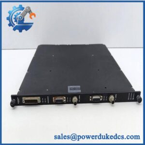
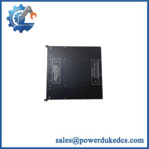
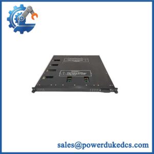
A discrete-input failure can appear to be a field-device problem when the actual fault is at the Tricon I/O interface. The TRICONEX 3525A is identified in current industrial inventory records as a Tricon digital input module. Its role is to acquire discrete field states and transfer the corresponding input information into the Tricon control architecture for processing by the redundant controller channels.
Public technical evidence for the exact 3525A designation is limited and does not reliably establish a complete electrical specification set. In particular, available records do not provide sufficiently authoritative confirmation of the exact channel count, field-input voltage range, input thresholds, or termination-panel reference. Those values should therefore be taken from the physical nameplate and the applicable Tricon hardware manual rather than inferred from similarly numbered Tricon I/O modules.
Module 4: Application Scenarios & Field Realities
- Within a Tricon safety-system I/O rack, the 3525A can be used to acquire discrete status information such as switch states, permissives, alarms, and equipment feedback. The common troubleshooting mistake is replacing the field device before checking the I/O channel and termination path.
- When several discrete indications fail simultaneously, inspect the shared field supply, termination assembly, I/O cable, and rack interface first. A common wiring or termination problem can affect several input points without indicating an internal module failure.
- During a brownfield Tricon cabinet replacement, preserve the original channel map and termination documentation. The 3525A should be matched by exact model and hardware configuration rather than substituted solely because another Tricon digital-input module has a similar enclosure.
- For surplus inventory management, record the complete nameplate information, including manufacturing codes and hardware revision. Current public listings confirm the 3525A as a Tricon digital input module, but do not provide enough primary documentation to support every electrical parameter.
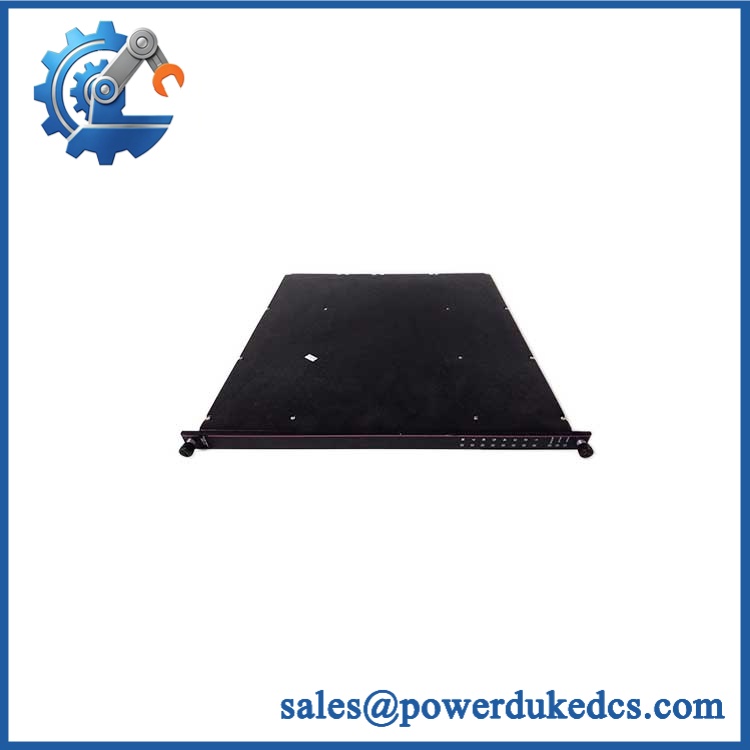
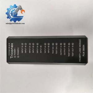
TRICONEX 3525A
Module 5: Migration, Compatibility & Installation Traps
Replacement Matrix
| Replacement Type | Assessment |
|---|---|
| Drop-in Replacement | Conditional — suitable only after exact Tricon system generation, hardware revision, input configuration, and termination arrangement are verified |
| Software Compatible | Conditional — verify Tricon configuration, I/O database, firmware, and controller revision |
| Hardware Modification Required | Normally no for a true like-for-like replacement; termination hardware and field wiring must match |
⚠️ Field Traps — Watch Out
1. Do not infer electrical specifications from other Tricon DI models.
Tricon has multiple digital-input families with different voltage ranges, channel configurations, and self-test characteristics. The publicly available evidence confirms the 3525A as a digital input module, but does not sufficiently establish its detailed electrical specification.
2. Verify the termination assembly before installation.
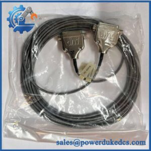
The input module and its field termination hardware form one electrical interface. Confirm the installed termination panel, cable, connector arrangement, and channel mapping against the cabinet documentation.
3. Preserve the existing channel assignment.
A module can pass its electronic diagnostic test while the cabinet still produces incorrect process states if field conductors are landed on the wrong channels.
4. Confirm the installed Tricon generation.
Do not assume that every module using a “35xx” designation belongs to the same controller generation. Hardware compatibility must be checked against the actual Tricon chassis and I/O architecture.
Module 6: Quality Assurance SOP
- OEM anti-counterfeit visual inspection — inspect TRICONEX markings, 3525A identification, serial/assembly labels, connector construction, housing, and visible manufacturing details.
- Exact part-number verification — confirm 3525A character-for-character against the purchase order and physical module label.
- Configuration verification — record the complete nameplate, hardware revision, manufacturing code, and any associated termination reference before testing.
- System-family verification — confirm the target Tricon chassis and I/O architecture from the customer’s cabinet documentation.
- Mechanical inspection — check backplane contacts, locking hardware, connector interfaces, housing, PCB surfaces, and mounting features for bent contacts, corrosion, contamination, cracks, or impact damage.
- Power-on self-test (POST) — energize the module in an approved Tricon test chassis and record startup status, diagnostic indications, current behavior, and abnormal temperature rise.
- Input simulation test — apply controlled discrete input states through an approved test fixture using the verified electrical configuration for the particular 3525A unit.
- Channel-by-channel verification — test every accessible input channel where the laboratory fixture supports the confirmed module configuration. Record applied state, detected state, and diagnostic result.
- Threshold verification — verify the actual input switching thresholds against the applicable OEM documentation rather than using thresholds from another Tricon digital-input model.
- Termination-path verification — perform point-to-point continuity checks between the module and the confirmed field termination assembly. Verify channel numbering and polarity where applicable.
- TMR/system verification — install the tested module in a compatible Tricon test environment and confirm correct module recognition, input processing, and diagnostic reporting across the redundant controller architecture.
- Communication handshake verification — verify module communication at the complete Tricon I/O-system level. This is not a standalone Ethernet or serial interface test.
- Fault simulation — use an approved diagnostic fixture to introduce permissible input or field-wiring faults and confirm the expected diagnostic response.
- Final QC and packaging — document the exact model, revision, tested channel configuration, diagnostic status, photographs, ESD protection, and packaging condition before shipment.
Engineering note: The TRICONEX 3525A is currently identifiable as a Tricon digital input module, and this classification is supported by current industrial inventory records. However, the available public evidence is not sufficiently authoritative to publish a definitive channel count, input voltage, switching threshold, or termination-panel number for this exact designation. For a safety-system spare, those parameters should be verified against the physical module label and the applicable Tricon documentation before quotation or installation.



 Start Chat


