

Description
- Brand: TRICONEX
- Full Model Number: AO3481 / 3481
- System/Series Family: Tricon / Trident safety controller I/O architecture
- Core Function: Four-channel TMR analog output module generating controlled 4–20 mA signals for field actuators
- Top 3 Hardcore Specs: 4 commoned-return channels; 4–20 mA output; 12-bit resolution with FSD diagnostics
- Stock Status: Verify current New Surplus, Factory Sealed, or Fully Tested Refurbished condition before order
Module 3: Technical Product Introduction
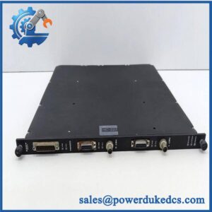
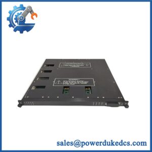
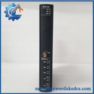
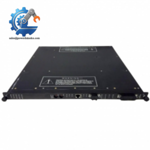
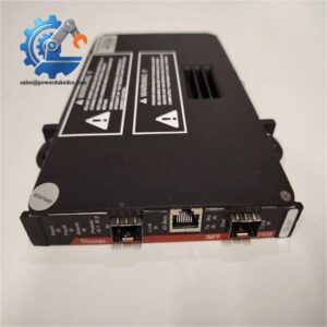
A process actuator does not simply need an output command; the safety system must also verify that the analog output path remains under control. The TRICONEX AO3481, also designated Model 3481, is a four-point TMR analog output module for Tricon/Trident safety-system architectures. Triconex documentation specifies four commoned-return, DC-coupled channels delivering controlled 4–20 mA signals. Internally, the module uses three identical isolated processing channels and output-selection circuitry so that the voted field signal is driven by the appropriate A, B, or C path.
The electrical specification is unusually specific. The 3481 provides 12-bit resolution, output accuracy better than 0.25% of full-scale range across 4–20 mA from 0°C to 70°C, a controlled 0–22 mA over-range, and forced-switch diagnostics on each point. The external loop supply is 24 VDC nominal, 32 VDC maximum, with load capability documented at 300 Ω above 16 VDC, 500 Ω above 20 VDC, and 700 Ω above 24 VDC. A leg failure is designed to produce an output-path switchover in approximately 1 ms typical and 3 ms maximum.
Module 4: Application Scenarios & Field Realities
- For control valves receiving 4–20 mA commands, AO3481 provides the analog output path from the Tricon/Trident safety application to the field actuator. The module is appropriate when the final element requires a standard current-loop command rather than a discrete energized/de-energized signal.
- In safety loops where output-path diagnostics matter, the TMR architecture is important. Each AO channel contains its own processing and DAC path, while the output selector votes the redundant signals before the field load is driven. This is a materially different architecture from a conventional single-board analog output card.
- When the field loop has substantial cable resistance or a demanding actuator input, calculate the complete loop burden before commissioning. The published 3481 requirements distinguish allowable load resistance according to available loop voltage; a nominal 24 VDC supply does not automatically guarantee a 700 Ω load can be driven.
- During live maintenance, the module supports hot-spare operation. Triconex documentation also states that AO modules are mechanically keyed to prevent installation into an incorrectly configured baseplate. That safeguard should remain intact; do not defeat the keying because a replacement appears mechanically close.
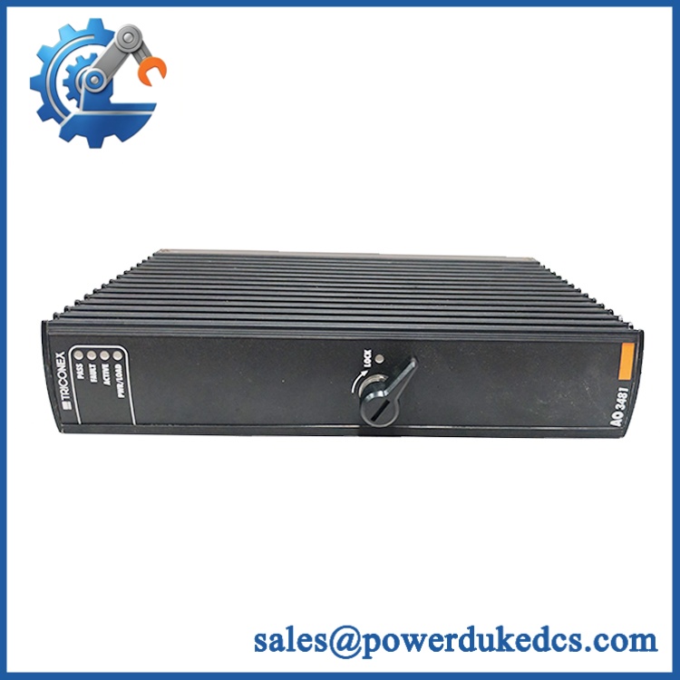
TRICONEX AO3481
Module 5: Migration, Compatibility & Installation Traps
Replacement Matrix
Exact AO3481 / 3481 with matching Tricon/Trident configuration: Drop-in Replacement
When the installed system uses the same 3481 module, approved baseplate, field termination arrangement, and controller configuration, replacement is normally a direct hardware exchange.
3481 with alternate supported baseplate: Hardware Verification Required
The 3481 is documented for Model 2481, 2483, 2483A, and an applicable external-termination baseplate arrangement. The correct choice depends on the system architecture, HART requirements, hazardous-location installation, and termination method.
3482 substituted for 3481: Hardware Modification Required
The 3482 is the high-current analog-output variant. Although both belong to the same Tricon/Trident analog-output family, their current capability and application requirements differ. A 3482 should not be treated as a universal replacement for 3481.
⚠️ Field Traps (Watch Out)
Loop-burden trap: The 3481’s output is 4–20 mA, but the allowable external load depends on available loop voltage. Published data specifies 300 Ω at greater than 16 VDC, 500 Ω at greater than 20 VDC, and 700 Ω at greater than 24 VDC. Measure the actual loop supply and calculate the installed burden before assuming full-scale current will be maintained.
Commoned-return trap: The four outputs are commoned-return and DC-coupled, not four independently isolated output loops. Review the field common arrangement before using AO3481 in a cabinet designed around individually isolated analog outputs.
Baseplate trap: The 3481 is mechanically keyed to its configured baseplate. Confirm the exact baseplate and termination arrangement before installation rather than relying on the module number alone.
Module 6: Quality Assurance SOP
Pre-Shipment QA Protocol for TRICONEX AO3481
- Step 1 — Identity Verification: Confirm TRICONEX marking, / 3481 model designation, serial number, hardware revision, manufacturing information, and associated baseplate information.
- Step 2 — OEM Anti-Counterfeit Visual Inspection: Examine labels, barcode information, PCB markings where accessible, connector geometry, mechanical keying, front-panel indicators, fasteners, and evidence of unauthorized component replacement.
- Step 3 — Mechanical Inspection: Check the module housing, card-edge connector, field interface, locking mechanism, alignment key, and enclosure for cracks, deformation, corrosion, contamination, or damaged contacts.
- Step 4 — Loop Test Fixture Verification: Prepare a calibrated 24 VDC loop supply and precision load fixture appropriate for a 4–20 mA analog-output test. Verify the test burden before energizing the module.
- Step 5 — Power-On Self-Test: Install the module in an approved Tricon/Trident test assembly and verify normal initialization, PASS/FAULT/ACTIVE indications, and absence of diagnostic faults.
- Step 6 — Four-Channel Output Test: Exercise all four output channels at representative points such as 4 mA, 12 mA, and 20 mA. Record measured current, output stability, and channel identification.
- Step 7 — Accuracy Verification: Compare measured output against calibrated reference equipment and verify performance against the documented accuracy specification over the intended operating range.
- Step 8 — Forced-Switch Diagnostic Test: Execute the approved FSD diagnostic procedure and verify that the module detects and handles controlled output-path fault conditions as expected.
- Step 9 — Redundancy and Failover Test: Where the laboratory setup permits, simulate an individual leg fault and verify the expected output-path transfer without an unsafe sustained output condition.
- Step 10 — Final QC Record: Record model, serial number, hardware revision, all four output measurements, loop-supply voltage, load resistance, FSD results, failover result, visual condition, test date, and final QC disposition.
Technical Verification Note: Triconex planning documentation identifies Model 3481 as a four-channel commoned-return TMR analog-output module with 4–20 mA controlled output, 12-bit resolution, forced-switch diagnostics, and 24 VDC nominal external loop power. The module supports hot sparing and is mechanically keyed to the configured baseplate.



 Start Chat


