

Description
- Brand: Triconex / Invensys
- Full Model Number: RO3451 / Model 3451
- System/Series Family: Trident
- Core Function: 32-point solid-state relay output switching for Trident safety and control systems
- Top 3 Hardcore Specs: 32 points commoned in pairs; ±24 V nominal input; 0.5 A nominal output current per channel
- Operating Voltage: ±30 V
- Maximum Switching Voltage: ±33 V peak
- Switching Power: 15 W resistive maximum
- Off-State Leakage: <100 µA
- Overcurrent: 0.7 A per channel maximum
- Voltage Drop: <0.25 V at 0.5 A at the baseplate
- Baseplate Fuse: 0.75 A fast-acting per output
- Isolation: 500 VDC functional-to-protective earth; 800 VDC functional-to-functional earth
- Associated Baseplate: Model 2451 SRO Baseplate
- Hot Spare: Supported
- Stock Status: New Surplus or Fully Tested Refurbished; exact revision to be confirmed
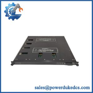
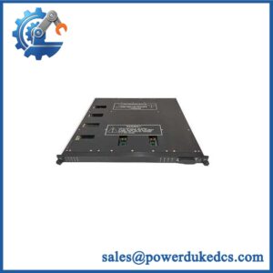
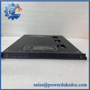
Triconex documentation identifies Model 3451 / RO3451 as the Trident Solid-State Relay Output Module, with 32 points commoned in pairs and compatibility with the Model 2451 SRO baseplate.
Module 3: Technical Product Introduction
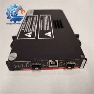
Relay feedback becomes important when the output device sits between the Trident controller and an auxiliary field circuit that cannot use a conventional high-side solid-state output. The TRICONEX RO3451, formally Model 3451, is a 32-point Solid-State Relay Output (SRO) module. Three isolated electronic channels receive output data from the associated Main Processors; the channels are voted, and the voted result drives the output relay circuitry. Triconex specifies the SRO architecture for non-critical output points that are not suited to high-side solid-state switches, such as annunciator interfaces.
The electrical envelope is unusually specific. The module uses ±24 V nominal input voltage, operates from ±30 V, and permits a maximum switching voltage of ±33 V peak. Maximum switching power is 15 W resistive, with 0.5 A nominal current per channel and 0.7 A maximum overcurrent. Off-state leakage is below 100 µA, while voltage drop at the baseplate is below 0.25 V at 0.5 A. Each output is protected by a 0.75 A fast-acting fuse mounted on the Model 2451 baseplate.
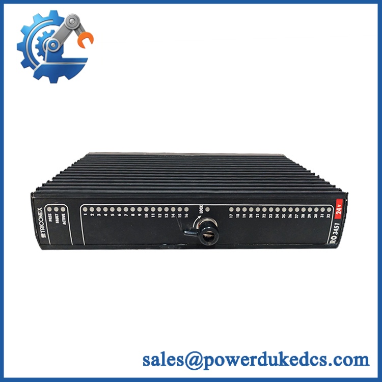
TRICONEX RO3451
Module 4: Application Scenarios & Field Realities
- For annunciator panels and auxiliary status circuits, RO3451 provides a relay-style output interface where a conventional high-side solid-state output is unsuitable. The Trident guide specifically describes the SRO module for non-critical points, including annunciator-panel interfaces.
- When several auxiliary devices share a Trident I/O column, the 32-point architecture gives the cabinet designer a high-density output interface while maintaining separate monitoring paths on the controller side. The points are commoned in pairs, so the field wiring scheme must be checked before treating each channel as fully independent.
- For online-maintenance programs, the SRO module supports hot sparing. The replacement process still depends on the active/spare configuration and the correct baseplate; simply removing an active module without following the approved Trident maintenance procedure is not an acceptable substitution strategy.
- Where a field load approaches 0.5 A, calculate the steady-state current and switching power rather than sizing from voltage alone. At the published 15 W resistive limit, the actual load type, inrush behavior, suppression components, and cable resistance can determine whether the circuit remains within specification.
Module 5: Migration, Compatibility & Installation Traps
Replacement Matrix
Replacement classification: Drop-in Replacement when the installed system is a compatible Trident 3451/RO3451 configuration using the Model 2451 SRO baseplate, matching field wiring, and the same system architecture.
Software compatibility: Configuration verification required. RO3451 is an I/O hardware module, but its channel assignments, output states, diagnostics, and hot-spare configuration remain part of the Trident controller configuration.
Cross-model replacement: Hardware and application verification required. A different Triconex digital-output module may use different switching topology, voltage range, load capacity, baseplate, or diagnostic behavior. The 3451 should not be substituted merely because another module provides 24 V digital outputs.
Field Traps — Watch Out
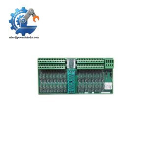
1. Match the Model 2451 baseplate. Triconex specifically identifies the 2451 SRO Baseplate as the compatible baseplate for Model 3451. The baseplate carries the output fuses and field connections, so changing the baseplate can change the electrical behavior of the installation.
2. Check commoned-pair wiring. The 32 points are specified as commoned in pairs. Before replacement, compare the field wiring diagram with the actual terminal assignment; an apparently independent load circuit may share the configured common with its paired point.
3. Do not exceed the resistive switching limit. The published maximum switching power is 15 W resistive, with 0.5 A nominal current per channel. Inductive loads, solenoid coils, and relay coils require separate consideration of suppression and transient energy. A simple DC resistance measurement does not fully characterize the switching duty.
4. Inspect the baseplate fuses during troubleshooting. Each output uses a 0.75 A fast-acting fuse on the Model 2451 baseplate. A blown fuse can create an apparent output-module failure even when the electronics are healthy. Diagnose the field circuit before replacing the module.
5. Do not confuse SRO functionality with a fully triplicated field output. The input side of the module has three isolated channels and voter logic, but the documentation explicitly describes the output portion as Simplex and the SRO as a non-triplicated module intended for non-critical points. That distinction matters during SIS architecture review.
Module 6: Quality Assurance SOP
Pre-Shipment Inspection Protocol for TRICONEX
- OEM identity inspection: Verify Triconex marking, / Model 3451 designation, hardware revision, serial number, front-panel markings, and additional assembly identifiers.
- Architecture verification: Confirm that the unit is the Trident Model 3451 Solid-State Relay Output Module and not a similarly numbered digital-output assembly.
- Mechanical inspection: Examine the enclosure, module guides, locking mechanism, front-panel indicators, connectors, PCB surfaces, and mounting interfaces for corrosion, contamination, cracks, deformation, or unauthorized modification.
- Baseplate verification: Test the module only with a compatible Model 2451 SRO baseplate and inspect the mating interface for bent, oxidized, or contaminated contacts.
- Power-on self-test: Energize the module in a compatible Trident test system and verify PASS, FAULT, ACTIVE, and LOCK status behavior.
- 32-point verification: Exercise all 32 output points independently under controlled laboratory conditions.
- Voltage-range test: Apply representative positive and negative supply conditions within the documented ±30 V operational range, without exceeding the published absolute switching limits.
- Load test: Apply calibrated resistive loads representative of the intended field circuit and verify switching performance, output stability, current, and thermal behavior.
- Current-limit verification: Confirm representative operation at currents below the 0.5 A nominal per-channel rating, while documenting protective behavior during controlled overcurrent testing where the laboratory procedure permits.
- Leakage verification: Measure Off-state leakage and confirm it remains below the published 100 µA maximum under the applicable test conditions.
- Voltage-drop verification: Measure output-path voltage drop under a controlled 0.5 A load and compare the result with the published <0.25 V baseplate specification.
- Fuse verification: Inspect the associated 0.75 A fast-acting baseplate fuses and verify correct fuse type, seating, and condition for all applicable output points.
- Loop-back diagnostic verification: Exercise the output diagnostic path and confirm that controlled relay/output faults are detected as expected.
- TMR input-path verification: Where the test bench permits, validate the three isolated input channels and voter behavior rather than qualifying the module only through field-side switching.
- Hot-spare test: Use a compatible active/spare Trident arrangement to verify online transfer according to the approved maintenance procedure.
- Thermal observation: Run representative multi-channel loads for an extended interval and inspect for abnormal heating, intermittent diagnostics, output drift, or fuse-related faults.
- Final QC record: Record exact model, revision, serial number, baseplate used, supply voltage, load values, all 32 output results, leakage, voltage-drop measurements, diagnostic results, fuse condition, hot-spare result where applicable, test date, and inspector approval.
- ESD-controlled packaging: Place the module in an ESD-safe package and protect its connectors, locking mechanism, LEDs, and PCB surfaces against impact, moisture, contamination, and electrostatic discharge.
Procurement note: The technically supported identity is TRICONEX / Model 3451 — Trident Solid-State Relay Output Module. The authoritative Trident specifications define 32 points commoned in pairs, ±24 V nominal input, ±30 V operating range, ±33 V peak maximum switching voltage, 15 W resistive switching power, 0.5 A nominal current per channel, <100 µA off-state leakage, 0.7 A maximum overcurrent, and 500/800 VDC isolation. The correct companion hardware is the Model 2451 SRO Baseplate.



 Start Chat


