

Description
- Brand: ALSTOM
- Full Model Number: 029.144.456
- System/Series Family: ALSTOM Industrial Control System
- Core Function: OEM industrial control-system module; exact functional designation requires confirmation from the equipment documentation
- Top 3 Hardcore Specs: ALSTOM OEM part number; 029.144.456 assembly reference; application-specific hardware
- Part Number Format: 029.144.456
- Module Type: Application-specific control hardware
- Interface: Configuration dependent
- Protocol: Not reliably established from the part number alone
- Stock Status: New Surplus / Factory-Sealed or Fully Tested Refurbished subject to actual inventory condition
Module 3: Technical Product Introduction
The ALSTOM 029.144.456 should be treated as an OEM-specific industrial control component rather than assigned a generic PLC or I/O function based solely on its catalog number. For replacement work, the complete part number is the primary identification reference. The available public information is insufficient to establish a reliable processor type, I/O count, rated voltage, communication protocol, or exact system family without risking a false specification.
That distinction matters for procurement. ALSTOM has supplied control equipment across power-generation, turbine, traction, and industrial applications, and similar-looking assemblies can have very different electrical functions. For 029.144.456, technical values should be taken from the original nameplate, equipment BOM, applicable ALSTOM documentation, or a clear PCB/module photograph. Avoid treating unverified catalog data as a replacement specification.
Module 4: Application Scenarios & Field Realities
- During legacy ALSTOM control-system maintenance, the complete 029.144.456 identifier should be matched before removing the existing module. A visually similar board is not sufficient evidence of compatibility.
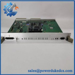
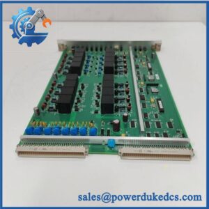
- For emergency spare-part replacement, compare the module’s connector arrangement, PCB markings, revision information, and installed rack position against the failed unit. Those details can identify the actual hardware function when public documentation is limited.
- When troubleshooting an unavailable or obsolete control module, inspect the surrounding power supply, backplane, I/O wiring, and communication hardware first. A module alarm does not necessarily prove that the module itself has failed.
- In long-term spare inventory, retain photographs of both sides of the PCB and the complete identification label. This is particularly useful for older ALSTOM assemblies whose public documentation is difficult to locate.
Module 5: Migration, Compatibility & Installation Traps
Replacement Matrix
| Replacement Case | Classification | Engineering Requirement |
|---|---|---|
| 029.144.456 → identical 029.144.456 | Drop-in Replacement | Verify complete part number, revision, connectors, and host-system configuration |
| Same part number with a documented compatible revision | Software Compatible | Confirm firmware/application compatibility where applicable |
| Different ALSTOM module with similar physical appearance | Hardware Modification Required | Full electrical and functional verification required |
| Generic PLC/I/O substitute | Hardware Modification Required | Not acceptable without complete engineering validation |
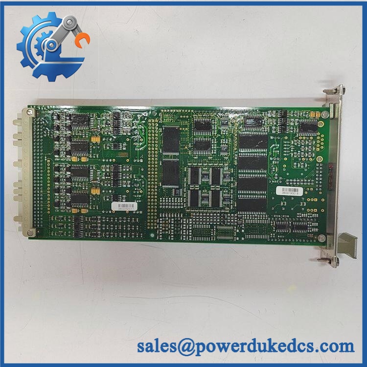
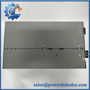
ALSTOM 029.144.456
Field Traps — Watch Out
1. Do not infer the function from the part number.
The designation 029.144.456 alone does not reliably establish whether the hardware is an I/O module, processor, power interface, communication assembly, or application-specific controller.
2. Revision and assembly information must be preserved.
If the physical unit has additional markings such as a revision code, serial number, PCB number, or secondary ALSTOM reference, record them before replacement. Those markings may distinguish otherwise similar assemblies.
Installation note: Isolate the equipment according to the applicable site procedure before removing the module. Photograph connector positions and record the original rack location. Do not reconnect field wiring until pin assignments have been verified against the applicable documentation.
Module 6: Quality Assurance SOP
For ALSTOM 029.144.456, QA should emphasize exact identification and controlled verification because reliable public technical specifications are limited.
- Part-number verification: Confirm 029.144.456 against the physical module and purchase record.
- OEM anti-counterfeit visual inspection: Examine ALSTOM markings, labels, PCB identifiers, revision codes, component layout, connectors, and manufacturing information.
- Secondary identification check: Record every additional part number, PCB number, revision, and serial/manufacturing code visible on the assembly.
- Mechanical inspection: Check the PCB, housing, connectors, mounting points, terminal blocks, card guides, and locking mechanisms.
- Component inspection: Look for corrosion, contamination, overheating, cracked components, damaged connectors, loose hardware, or unauthorized repairs.
- Power verification: Apply power only in an approved test environment after the applicable supply requirements have been confirmed from authoritative documentation.
- Power-on self-test (POST): Where the module contains active electronics, verify normal startup and applicable status/diagnostic indications.
- I/O verification: Test only the input/output channels confirmed by the applicable ALSTOM documentation; do not assume channel functions from connector appearance.
- Communication handshake verification: Where a communication interface is confirmed, establish communication with the appropriate host/test controller and verify diagnostic status.
- Functional verification: Execute the documented module-specific test procedure using calibrated equipment.
- Thermal observation: Monitor the module during an extended controlled run for abnormal heating or intermittent behavior.
- Final inspection: Recheck connectors, labels, PCB condition, mounting hardware, and protective packaging.
- Traceability: Record complete part number, revision, secondary identifiers, serial information where available, test equipment, test results, inspection date, and condition classification.
Procurement note: For ALSTOM 029.144.456, it is safer to publish only specifications that can be verified from the physical unit or authoritative documentation. I would not assign a specific voltage, protocol, I/O count, weight, or application to this part without additional evidence. This prevents a technically incorrect PDP from creating a replacement-compatibility problem.



 Start Chat


