

Description
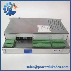
- Brand: ALSTOM / Converteam
- Full Model Number: PIB101C
- System / Series Family: ALSPA / Converteam VME-based control systems
- Core Function: Analog I/O and power-interface board for ALSTOM/Converteam control architectures
- Top 3 Hardcore Specs: PIB101C / Part No. 3BD91299 / VME-based control-system interface
- Board Type: Analog I/O Power Interface Board
- Related Part Number: 3BD91299; some inventories identify 3BD91299-B
- Application: ALSPA power-conversion and industrial control systems
- Architecture: VME-based
- Stock Status: New Surplus / Factory Sealed — exact physical condition and suffix to be confirmed before quotation
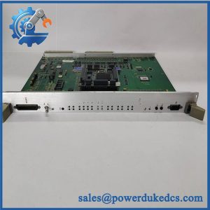
The PIB101C is identified in multiple equipment references as an ALSTOM/Converteam PCB module, with 3BD91299 and 3BD91299-B appearing as associated part-number references. An ALSTOM training document also specifically lists PIB101C within its power-conversion equipment documentation.
Module 3: Technical Product Introduction
A failed interface board in an older ALSPA control rack can interrupt both signal handling and the associated control-system interface, even when the VME backplane and processor remain operational. The ALSTOM PIB101C is identified as an Analog I/O Power Interface Board associated with ALSTOM/Converteam VME-based control systems. Public equipment references associate the model with 3BD91299, while another documented inventory variant is marked 3BD91299-B. That suffix should be treated as significant during procurement until the customer’s equipment documentation confirms equivalence.
The strongest technical evidence places PIB101C within ALSTOM Power Conversion equipment rather than a generic PLC I/O family. An ALSTOM training document for electrical propulsion equipment explicitly lists alongside other PIB modules used within the control architecture. Exact channel counts, signal ranges, power ratings, and connector pin assignments are not sufficiently established by the available documentation, so those values should not be copied from unrelated PIB models. —For a legacy VME assembly, the equipment BOM and original PCB markings remain the controlling references.
Module 4: Application Scenarios & Field Realities
- In ALSTOM Power Conversion VME cabinets, the can form part of the interface between field-level analog signals and the control electronics. Confirm the board’s exact rack position and associated wiring before removal.
- For electrical propulsion control equipment, is specifically referenced in ALSTOM training documentation. This makes the complete board identification important when maintaining older propulsion-control installations rather than substituting a generic analog I/O card.
- During a VME rack outage, inspect the together with the rack power supply, backplane, adjacent interface boards, and field wiring. A PCB failure may originate from an external signal or power fault.
- When the existing board carries a 3BD91299-B marking, do not automatically substitute a marked only 3BD91299. Compare revision information, connector arrangement, and equipment documentation first. Both identifiers appear in current inventory references, but that alone does not prove interchangeability.
Module 5: Migration, Compatibility & Installation Traps
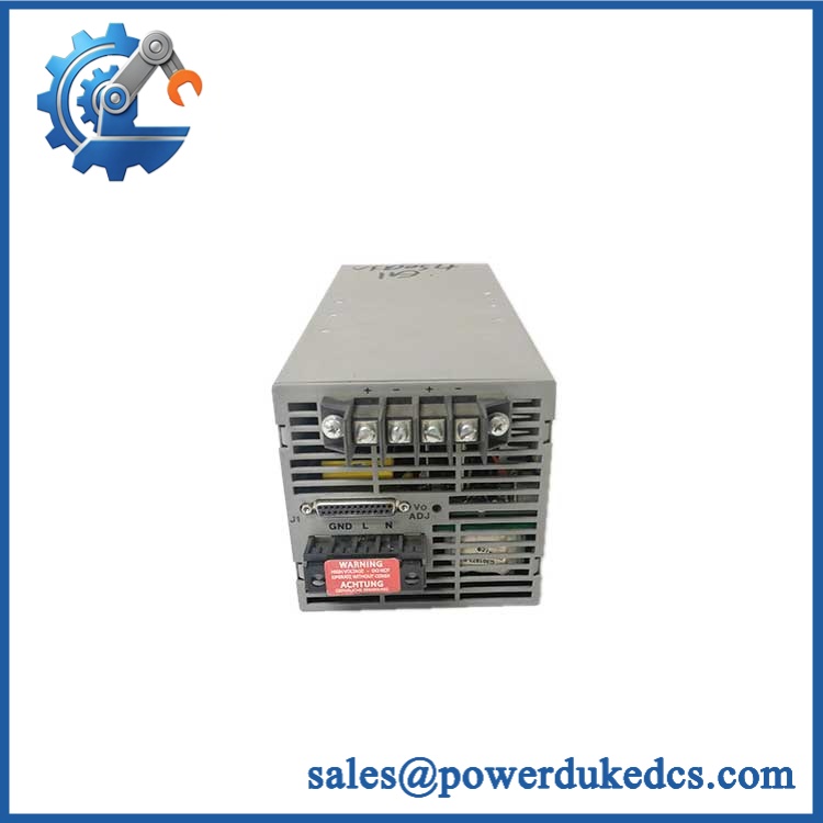
ALSTOM PIB100G 3BEE0226
Replacement Matrix
| Replacement Case | Classification | Engineering Requirement |
|---|---|---|
| replacing the identical | Drop-in Replacement | Verify complete board marking, revision, rack position, connectors, and application |
| 3BD91299 replacing 3BD91299-B | Software Compatible — Verify First | Confirm revision equivalence and equipment-specific documentation |
| Different PIB-series board | Hardware Modification Required | Verify signal types, power interface, connector pinout, and VME configuration |
| Modern I/O module replacing | Hardware Modification Required | Engineer signal conversion, VME/interface replacement, wiring, software, and commissioning |
Field Traps — Watch Out
3BD91299 versus 3BD91299-B: Both references appear in available product records for . Do not assume the suffix is cosmetic. The replacement should match the original assembly marking or be supported by an approved interchangeability record.
Do not assume generic analog specifications: Some commercial listings describe as an analog I/O board but provide conflicting electrical specifications. Treat unsupported voltage, current, channel-count, and protocol claims as unverified until confirmed by the ALSTOM equipment documentation.
VME rack position: Record the original slot and neighboring modules before removal. The physical board may fit multiple positions while the control application expects a specific rack location.
Connector mapping: Photograph every connector and cable designation. Never reconnect a legacy VME interface solely by connector shape.
Power-stage fault investigation: If the failed during a converter or propulsion-system fault, inspect the associated power supply and field circuits before installing the replacement. Otherwise, the replacement may be exposed to the same fault.
Module 6: Quality Assurance SOP
The pre-shipment inspection for an ALSTOM should emphasize exact board identification, revision control, connector integrity, and controlled VME-system testing:
- Part-number verification — Confirm the physical identification as and record every visible ALSTOM, Converteam, 3BD91299, and revision marking.
- OEM anti-counterfeit visual inspection — Examine labels, PCB artwork, component markings, connectors, solder joints, assembly identifiers, and manufacturing details for inconsistent printing or unauthorized modification.
- Mechanical inspection — Check the PCB substrate, mounting points, VME contacts, connectors, terminal interfaces, and accessible components for cracks, deformation, corrosion, contamination, or impact damage.
- Revision verification — Determine whether the board is marked 3BD91299, 3BD91299-B, or another documented variant. Record the exact marking in the QA report.
- Connector inspection — Examine all connectors for bent contacts, damaged housings, oxidation, contamination, loose pins, or evidence of arcing.
- PCB component inspection — Check capacitors, resistors, ICs, transformers, and other accessible components for swelling, discoloration, cracking, overheating, or previous repair.
- Power-on self-test (POST) — Where an approved ALSTOM/Converteam test rack and verified electrical specification are available, power the board under controlled conditions and inspect applicable status and diagnostic indications.
- VME interface verification — Install the in a compatible VME test environment and verify correct rack recognition and expected backplane interaction.
- Analog I/O screening — Test applicable input and output channels against the correct equipment-specific test procedure. Do not apply assumed signal levels where the exact specification has not been established.
- Communication handshake verification — If the customer’s configuration uses a communication path associated with the board, verify it against the applicable ALSTOM system documentation rather than assuming a generic protocol.
- System-interface verification — Where a compatible ALSPA/Converteam simulator or test rack is available, confirm the board’s expected interaction with the associated control architecture.
- Final inspection and packaging — Photograph the exact and 3BD91299/3BD91299-B markings, record all test results, protect VME contacts and connectors, apply appropriate ESD precautions, and package the board against mechanical shock and moisture.
The final QA record should link the model, exact 3BD91299 revision, PCB condition, connector inspection, VME test, applicable analog-I/O screening, system-interface verification, and packing record to the exact unit shipped. For this ALSTOM board, revision identification is particularly important because both 3BD91299 and 3BD91299-B references appear in available records.



 Start Chat


