

Description
- Brand: FOXBORO
- Full Model Number: FBM201 RH914SQ
- System/Series Family: Foxboro I/A Series Standard 200 Series FBM
- One-Sentence Core Function: Eight-channel galvanically isolated analog input interface for 0–20 mA DC field signals
- Top 3 Hardcore Specs: 8 isolated channels; 0–20 mA DC input; redundant 2 Mbps Module Fieldbus
- Stock Status: New Surplus / Fully Tested Refurbished — verify termination assembly and baseplate configuration before shipment
Module 3: Technical Product Introduction
When several process transmitters disappear from the DCS at the same time, the problem often sits at the common I/O interface rather than at the individual instruments. The FOXBORO FBM201 RH914SQ is an I/A Series analog input interface module providing eight independent, galvanically isolated channels, each designed for 0–20 mA DC analog input. Schneider Electric’s current documentation specifically identifies RH914SQ as the part number for the Standard 200 Series FBM201.
Each channel performs its own analog-to-digital conversion using an independent sigma-delta converter, while the module communicates with its associated Foxboro control equipment through a redundant 2 Mbps Module Fieldbus. The documented module dimensions are approximately 102 × 45 × 104 mm, or 114 mm high including mounting lugs, with a module weight of approximately 284 g. The RH914SQ designation is important: FBM201b, FBM201c, and FBM201d are different input variants for 0–100 mV, 0–5 V, and 0–10 V signals.
Module 4: Application Scenarios & Field Realities
- On refinery, chemical, and utility process loops, the FBM201 can collect multiple 0–20 mA transmitter signals such as pressure, flow, level, and process-temperature transmitter outputs. Because the eight channels are galvanically isolated from one another and ground, a fault on one analog loop does not simply become a common electrical connection to every channel.
- When one transmitter value becomes implausible while the remaining seven channels remain normal, test the individual loop current before condemning the FBM. Each FBM201 input has its own signal-conversion path, so a controlled current injection is much more informative than replacing the whole module immediately.
- For brownfield I/A Series maintenance, verify the termination assembly before installation. The FBM201 uses separate termination assemblies and can be connected locally or remotely, with documented termination cables up to 30 m. The baseplate-side connection uses a 37-pin D-subminiature, while the main termination-assembly side uses a 25-pin D-subminiature.
- Where existing transmitters use 4–20 mA, the ‘s 0–20 mA input span accommodates that signal range because 4–20 mA is contained within the specified input range. Do not, however, substitute an for the voltage-input variants simply because their front housings look similar. The FBM201b/c/d variants have different electrical input ranges.
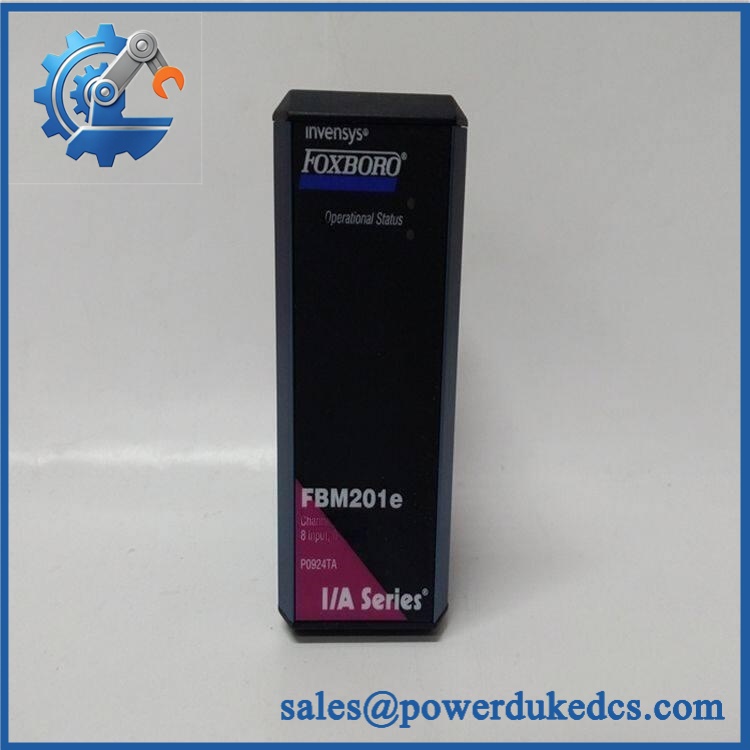
FOXBORO FBM201 RH914SQ
Module 5: Migration, Compatibility & Installation Traps
Replacement Matrix
| Replacement Type | Assessment |
|---|---|
| Drop-in Replacement | Yes, for an exact RH914SQ replacement in a compatible Standard 200 Series installation |
| Software Compatible | Normally yes within the supported I/A Series configuration, but hardware database and control-system revision should still be checked before commissioning |
| Hardware Modification Required | Normally no for an exact replacement; baseplate, termination assembly, cabling, and channel configuration must match |
⚠️ Field Traps — Watch Out
1. Do not confuse RH914SQ with the other variants.
Schneider’s documentation identifies specifically as , whose input is 0–20 mA DC. FBM201b uses RH922YH for 0–100 mV, FBM201c uses RH922YJ for 0–5 V, and FBM201d uses RH922YK for 0–10 V. Those are not electrical drop-in equivalents.
2. The termination assembly is part of the replacement check.
Do not disconnect the field wiring until the installed TA, termination cable, and channel numbering have been photographed and matched to the cabinet documentation. Schneider specifies termination cables up to 30 m, with defined 37-pin and 25-pin D-sub connections.
3. Do not treat 0–20 mA as a generic PLC input specification.
The is an I/A Series FBM communicating over the Foxboro 2 Mbps Module Fieldbus. A generic PLC analog-input module cannot be substituted merely because its input range is also 0–20 mA.
4. Preserve the existing channel mapping.
During replacement, record each transmitter’s channel number and field termination. A correctly functioning replacement module can still create incorrect process values when conductors are landed on the wrong channels.
Module 6: Quality Assurance SOP
- OEM anti-counterfeit visual inspection — inspect FOXBORO identification, marking, label, housing, connectors, PCB condition, mounting features, and visible manufacturing identifiers.
- Exact part-number verification — confirm against the purchase order and physical label. Schneider Electric lists as the Standard 200 Series part number.
- Input-type verification — confirm that the unit is the 0–20 mA rather than FBM201b/c/d voltage-input variants.
- Mechanical inspection — check the housing, mounting lugs, baseplate connector, termination interface, and PCB surfaces for cracks, bent contacts, corrosion, contamination, or impact damage.
- Power-on self-test (POST) — install the module in an approved test baseplate and energize it under the documented system conditions. Record startup status, diagnostic indications, current behavior, and abnormal temperature rise.
- Analog input simulation — apply controlled current signals to representative channels, including 4 mA, 12 mA, and 20 mA, using a calibrated loop simulator. Record the measured digital values rather than relying solely on status indication.
- Eight-channel verification — test all eight input channels where the laboratory fixture permits. Record channel-by-channel response and identify any abnormal offset, noise, or conversion behavior.
- Isolation verification — perform the applicable channel-to-channel and channel-to-ground isolation test using the approved maintenance procedure and test voltage. Avoid applying an uncontrolled hipot test directly to connected electronics.
- Module Fieldbus verification — establish communication with a compatible Foxboro FCM/FCP test environment over the documented redundant 2 Mbps Module Fieldbus and confirm module recognition and stable process-data exchange.
- Termination-path verification — inspect and, where practical, continuity-test the complete termination path between the FBM baseplate connection and the field termination assembly.
- Configuration verification — compare the tested module against the intended I/A Series control database and channel assignments before releasing it for installation.
- Final QC and packaging — record part number, revision information, eight-channel test results, fieldbus test result, label photographs, ESD protection, and packaging condition before shipment.
Engineering note: The exact identification FOXBORO is well supported by Schneider Electric’s current product specification: is the Standard 200 Series , an eight-channel isolated 0–20 mA DC analog input module. The termination assembly and field wiring should be considered part of the replacement specification, particularly in an existing I/A Series installation.




 Start Chat


