

Description
- Brand Foxboro
- Full Model Number FBM202 P0926EQ
- System/Series Family Foxboro I/A Series 200 Series FBM
- Core Function Eight-channel isolated thermocouple and millivolt signal input interface
- Top 3 Hardcore Specs 8 thermocouple/mV inputs | 1 isolated RTD reference-junction compensation channel | Galvanically isolated input channels
- Stock Status New Surplus — verify hardware revision, termination assembly, and sensor configuration before shipment
Module 3: Technical Product Introduction
A failed temperature-input channel can make a healthy DCS appear to have a process problem. The Foxboro FBM202 P0926EQ is an I/A Series 200 Series fieldbus module designed for eight thermocouple input channels, with one isolated RTD reference-junction compensation channel for terminal-temperature sensing. Each thermocouple/mV input is galvanically isolated from the other channels and from ground, and the module performs the signal conversion needed to place field temperature measurements onto the Foxboro fieldbus. Schneider Electric’s current product specification identifies P0926EQ as the termination-assembly reference associated with the FBM202 architecture, while product documentation identifies the module itself as an eight-input thermocouple/mV interface.
The FBM202 uses sigma-delta conversion to achieve high input accuracy and includes configurable analog-input application functions such as integration time and rate-of-change limits. Thermocouple burnout detection is also provided, with the documented failure response driving the affected indication upscale. The module can be mounted on a DIN rail or installed horizontally in a 19-inch rack with the appropriate mounting hardware; the published module weight is approximately 284 g. For a replacement, the critical checks are sensor type, termination assembly, channel mapping, and the existing I/A Series configuration—not simply whether the spare fits the carrier.
Module 4: Application Scenarios & Field Realities
- On refinery furnace and reactor temperature loops, the FBM202 can acquire multiple thermocouple signals while keeping each input electrically isolated. That channel isolation is useful when thermocouples originate from equipment with different grounding conditions or long field cable runs.
- For high-temperature process monitoring, thermocouple burnout detection provides another diagnostic layer beyond simple signal conversion. When a sensor circuit opens, the documented upscale burnout response can help distinguish a failed field sensor from a genuine high-temperature process excursion.
- Where many temperature points terminate in one I/A Series cabinet, the eight-channel architecture reduces the number of individual field interfaces required. During a shutdown replacement, however, channel-to-tag mapping must be preserved exactly; swapping two thermocouple channels can create a credible-looking but incorrect process reading.
- During migration from older 100 Series equipment, Foxboro documentation states that the FBM202 can provide functionality formerly supplied by the 100 Series FBM I/O subsystem when used with the appropriate termination assemblies. That makes the termination hardware part of the migration equation, not an optional accessory.
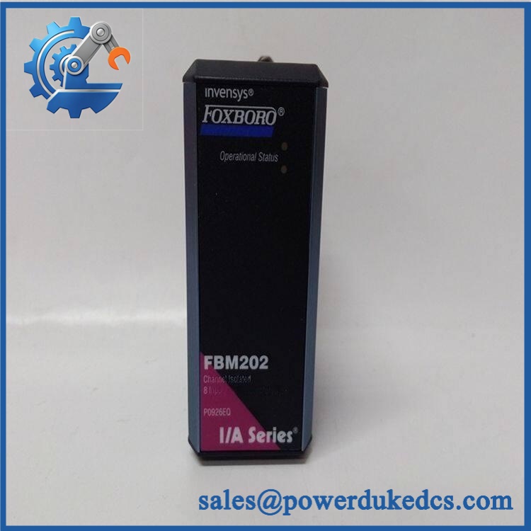
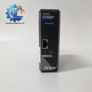
Foxboro FBM202 P0926EQ
Module 5: Migration, Compatibility & Installation Traps
Replacement Matrix
| Replacement Status | Engineering Assessment |
|---|---|
| Drop-in Replacement | Yes, for a like-for-like P0926EQ installation with the same approved I/A Series carrier, termination assembly, firmware baseline, and field-channel configuration. |
| Software Compatible | Generally yes for an exact module replacement, but the I/A Series database, channel assignments, sensor types, scaling, burnout settings, and configured application parameters must be verified. |
| Hardware Modification Required | Normally no for an exact replacement. Changes may be required when migrating from a different FBM generation, termination architecture, or thermocouple wiring scheme. |
⚠️ Field Traps: Watch Out
Do not confuse the module number with the termination-assembly number. Current Schneider Electric documentation identifies the module separately and lists RH926EQ as the termination assembly, superseding P0926EQ. A purchase record containing “ P0926EQ” therefore needs to establish whether the buyer requires the actual electronics, the legacy P0926EQ termination reference, or both.
Verify the thermocouple type before reconnecting field wiring. Different thermocouple types have different EMF characteristics. The configured sensor type, polarity, extension cable, and cold-junction/reference arrangement must agree with the engineering database.
Do not substitute the module based on channel count alone. Some secondary listings incorrectly describe as a digital-input, RTD-only, or mixed-I/O device. Official Foxboro documentation identifies the function as eight isolated thermocouple/mV inputs plus one isolated RTD reference-junction compensation channel.
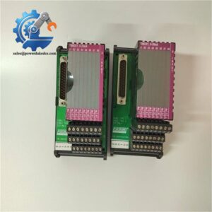
Check the termination assembly before bench testing. The has dedicated termination arrangements, including a baseplate-mounted assembly for paired slots and DIN-rail-mounted options. An incorrect TA can make a good FBM appear to have wiring or channel faults.
Module 6: Quality Assurance SOP
The is an analog temperature-acquisition module, so pre-shipment acceptance should focus on channel accuracy, isolation, burnout diagnostics, and termination compatibility.
- OEM anti-counterfeit visual inspection: Verify Foxboro identification, exact designation, -associated markings, PCB revision, enclosure, connectors, and manufacturer labels against controlled reference information.
- Part-number and traceability check: Record the module designation, revision, serial number, manufacturing/date codes, and any associated termination-assembly identification.
- Mechanical inspection: Examine the enclosure, backplane connector, field interface, mounting hardware, connector pins, and PCB for cracks, corrosion, contamination, bent contacts, or evidence of unauthorized rework.
- Power-on self-test (POST): Install the in an appropriate I/A Series test arrangement and verify normal startup and module diagnostic behavior.
- Supply verification: Apply the approved system supply using a controlled test fixture and monitor voltage stability and abnormal current consumption.
- Thermocouple-input test: Inject calibrated thermocouple or simulated thermocouple/mV signals into all eight channels and verify correct polarity, measurement, and channel identification.
- Reference-junction test: Verify the isolated RTD reference-junction compensation channel against a calibrated reference where the test fixture supports the complete measurement architecture.
- Isolation verification: Test channel-to-channel and channel-to-ground isolation according to the applicable Foxboro laboratory procedure.
- Burnout-detection test: Introduce a controlled open-circuit condition on representative thermocouple channels and verify the expected upscale burnout response and diagnostic indication.
- Accuracy verification: Test representative low-, mid-, and high-range thermocouple/mV points and compare the measured values with the applicable Foxboro tolerance.
- Integration-time and filtering verification: Confirm configured integration or signal-processing behavior where supported by the system test environment.
- Channel mapping verification: Match all eight physical channels against the approved tag list, termination positions, sensor types, and engineering ranges.
- System recognition test: Verify that the I/A Series system recognizes the and assigns the expected module and channel addresses.
- Communication handshake verification: Confirm successful fieldbus data exchange between the and the associated Foxboro control system. The test should verify actual process-value transmission rather than only module power status.
- Extended-run test: Operate the module with representative inputs while monitoring temperature values, diagnostic status, signal stability, and intermittent channel faults.
- Final QC record: Document revision, supply measurements, all eight channel test results, reference-junction verification, isolation results, burnout test, system recognition, communication status, traceability, and packing condition.
Technical Identification Note: Foxboro and Schneider Electric documentation consistently identifies as an 8-channel isolated thermocouple/mV input module with one isolated RTD reference-junction compensation channel. The documentation also identifies in the associated termination-assembly context, while newer termination hardware is referenced as RH926EQ. Secondary supplier pages contain conflicting descriptions, including digital-input and RTD-only classifications; those should not override the controlled Foxboro documentation.



 Start Chat


