

Description
- Brand: FOXBORO
- Full Model Number: FBM217
- System/Series Family: Foxboro I/A Series DCS / Standard 200 Series FBM
- One-Sentence Core Function: 32-channel discrete-input interface module for converting field contact or DC voltage signals to the Foxboro Module Fieldbus
- Top 3 Hardcore Specs: 32 isolated discrete inputs; 15–60 VDC input range; redundant 2 Mbps Module Fieldbus
- Stock Status: New Surplus / Fully Tested Refurbished — confirm exact termination assembly before shipment
Module 3: Technical Product Introduction
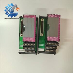
A failed digital-input interface can make an entire group of field status signals disappear from the DCS at once. The FOXBORO FBM217 provides 32 discrete input channels, with each channel accepting a two-wire input from a DC voltage source. Associated termination assemblies adapt the module for different field signal ranges, including 15–60 VDC, 120 VAC/125 VDC, and 240 VAC applications. The module converts these field signals for transmission over the Foxboro Module Fieldbus.
Electrical details depend on the selected termination assembly, so the TA cannot be ignored during replacement. For the documented 15–60 VDC configuration, the input operates from approximately 15 to 30 VDC in the on-state and 0 to 5 VDC in the off-state, with a typical input current of 2.2 mA at 30 VDC. Module power consumption is specified at approximately 3 W maximum at 24 VDC, and communications use a redundant 2 Mbps Module Fieldbus connection to the associated FCM or FCP.
Module 4: Application Scenarios & Field Realities
- On a refinery or chemical-process DCS cabinet, the FBM217 can collect valve limit switches, motor status contacts, alarms, and other binary field indications. With 32 channels available on one module, it is well suited to dense status-monitoring sections where multiple discrete signals return to one I/O location.
- When a group of field indications disappears together, check the FBM217 and its termination assembly before replacing individual field devices. The module is the signal-conversion point between the field wiring and the Module Fieldbus, so a single interface fault can affect many channels simultaneously.
- For AC or higher-voltage discrete signals, the installed TA becomes part of the functional specification. Foxboro documentation identifies TA-dependent support for signals below 60 VAC, 120 VAC/125 VDC, and 240 VAC, using attenuation, current-limiting, and optical-isolation circuitry where applicable. A standard 24 VDC termination arrangement should not be assumed interchangeable with a high-voltage TA.
- In redundant control architectures, the FBM217 can be installed as a redundant module pair. The control system treats the redundant modules as independent modules at the management-software level, while the redundancy function is handled through the associated control blocks.
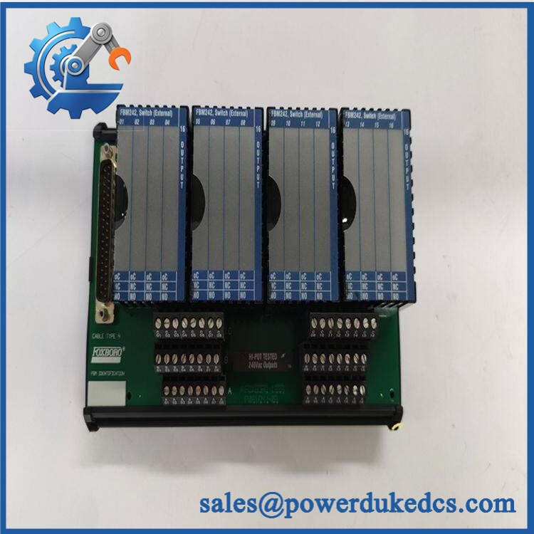
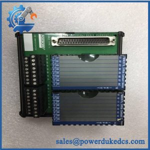
FOXBORO FBM217
Module 5: Migration, Compatibility & Installation Traps
Replacement Matrix
| Replacement Type | Assessment |
|---|---|
| Drop-in Replacement | Conditional — appropriate for an exact FBM217 replacement when the termination assembly, baseplate, field-voltage range, and system revision match |
| Software Compatible | Conditional — verify the installed Foxboro I/A Series software and control configuration before commissioning |
| Hardware Modification Required | Normally no for an exact replacement; TA type, baseplate connection, and redundant/non-redundant arrangement must match |
⚠️ Field Traps — Watch Out
1. The termination assembly determines the real field-input interface.
Do not order an based on the module number alone. Foxboro documentation identifies multiple TA arrangements supporting different voltage ranges, including low-voltage DC, 120 VAC/125 VDC, and 240 VAC applications.
2. Channel numbering must be preserved.
The documentation divides the 32 channels into main input channels 1–16 and expansion input channels 17–32. During replacement, retain the existing channel mapping rather than assuming the field wiring sequence can be rearranged.
3. Check the field threshold before substitution.
For the documented DC-input arrangement, the on-state range is 15–30 VDC and the off-state range is 0–5 VDC. A field device operating near the transition region deserves particular attention during commissioning.
4. Redundant applications require the correct system arrangement.
A redundant installation is not simply two modules placed side by side. Confirm the appropriate baseplate and redundancy configuration before commissioning the pair.
Module 6: Quality Assurance SOP
- OEM anti-counterfeit visual inspection — inspect FOXBORO identification, model markings, PCB labels, enclosure, connectors, mounting features, and visible manufacturing details.
- Exact part-number verification — confirm against the purchase order, physical label, and inventory record.
- Termination-assembly verification — identify the associated TA and verify that its voltage range and electrical architecture match the customer’s existing field signals.
- Mechanical inspection — examine the housing, baseplate interfaces, termination connectors, mounting points, and PCB surfaces for cracks, bent contacts, oxidation, contamination, or impact damage.
- Power-on self-test (POST) — energize the module under controlled conditions using the documented supply arrangement. Record startup behavior, status indications, current draw, and abnormal temperature rise.
- Channel simulation test — apply controlled discrete input states across representative channels, including valid on/off thresholds for the confirmed TA configuration.
- 32-channel functional verification — test the available channels according to the approved laboratory fixture and record the response channel by channel. Do not infer all-channel performance from a single successful point.
- Input isolation verification — where supported by the installed TA, verify the applicable channel or group isolation arrangement using the approved electrical test procedure.
- Communication handshake verification — establish the 2 Mbps Module Fieldbus connection with a compatible FCM/FCP test environment and verify stable module recognition and data exchange.
- Redundancy verification — where the spare is intended for redundant service, test the applicable redundant-pair behavior and confirm proper system recognition.
- Final QC and packaging — document the exact model, TA type, test results, channel verification status, label photographs, ESD protection, and packaging condition before shipment.
Engineering note: The strongest current evidence identifies as a 32-channel discrete input interface module for the Foxboro I/A Series. The module itself is not a universal 24 VDC-only input card; the actual field-voltage capability depends on the associated termination assembly. That TA should therefore be treated as part of the replacement specification, not as an optional accessory.



 Start Chat


