

Description
- Brand: Foxboro
- Full Model Number: FBM207B
- System/Series Family: Foxboro Evo Compact 200 Series I/O
- One-Sentence Core Function: 16-channel galvanically isolated 24 VDC contact-sense input module for discrete field signals
- Top 3 Hardcore Specs: 16 isolated input channels; 24 VDC ±15% contact-sense supply; 2 Mbps redundant Module Fieldbus
- Stock Status: Stock condition and hardware revision to be confirmed
Module 3: Technical Product Introduction
A failed discrete input module can remove multiple valve-position, limit-switch, motor-status, or interlock indications from the control strategy at once.
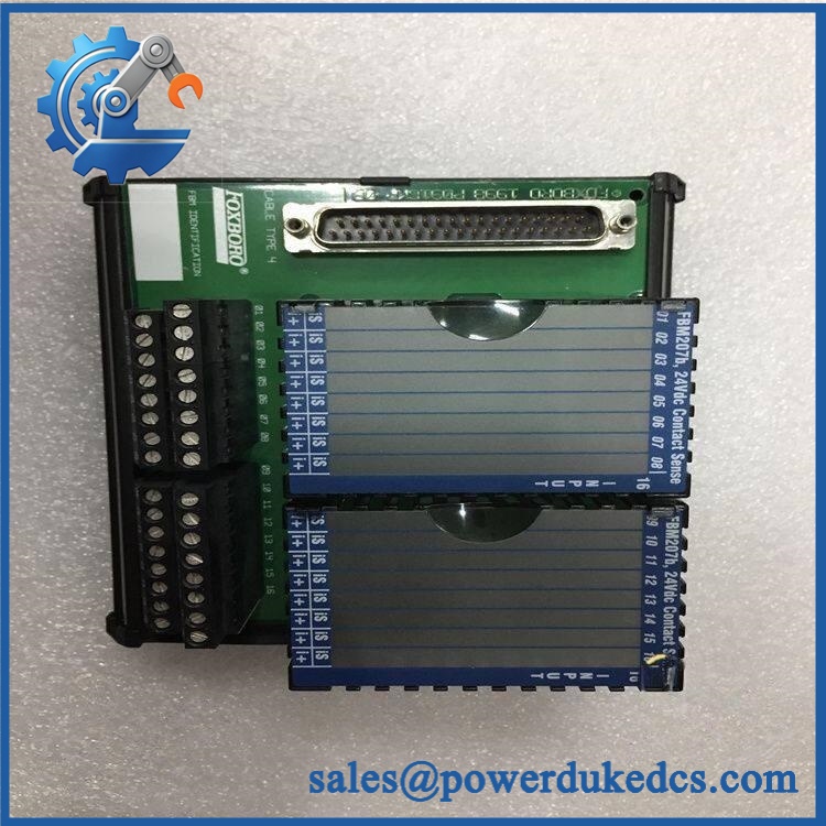
FBM207B
The module accepts pairs of contacts or solid-state switches and communicates with its associated Fieldbus Communications Module or Field Control Processor through the redundant 2 Mbps Module Fieldbus.
The input characteristics are defined tightly enough for field replacement work: 24 VDC ±15% open-circuit voltage, approximately 3.2 mA typical short-circuit current, a maximum 1.0 kΩ on-state resistance, and a minimum 100 kΩ off-state resistance. Pulse counting is supported through 250 Hz without missing pulses, while configurable debounce/filter settings include no filtering, 4, 8, 16, or 32 ms. Maximum module consumption is 5 W, and the operating temperature range is −20°C to +60°C
Module 4: Application Scenarios & Field Realities
- On valve limit switches and equipment permissives, FBM207B provides direct contact-state acquisition for the control system. Because each channel is isolated, an electrical fault on one field circuit is less likely to propagate through the input electronics; still, the field wiring and termination assembly must match the intended voltage arrangement.
- For motor and rotating-equipment status monitoring, the 16 discrete channels can collect auxiliary-contact indications such as run, stop, trip, breaker position, or permissive states. Where pulse-count functionality is used, the specified 0–250 Hz range should be checked against the actual device output before commissioning.
- In a redundant Foxboro Evo installation, two FBM207B modules can operate as a redundant pair through the RH101AZ redundant adapter. The modules must occupy adjacent odd/even baseplate positions, and a single termination assembly can feed the redundant pair through the adapter.
- For remote I/O cabinets, termination assemblies can be positioned separately from the FBM, with termination cables available up to 30 m / 98 ft. That permits the field wiring to remain at a convenient marshalling location while the FBM sits on the Compact 200 Series baseplate.
Module 5: Migration, Compatibility & Installation Traps
Replacement Matrix
Replacement Classification: Drop-in Replacement Within the Matching Compact 200 Series Configuration
A like-for-like FBM207B / FBM207b replacement is normally a direct module exchange when the existing system uses the same Compact 200 Series hardware, termination assembly, fieldbus arrangement, and application configuration. Schneider Electric identifies the Compact FBM207b as a 16-channel 24 VDC contact-sense module, with support for discrete input, ladder logic, pulse count, and Sequence of Events functions.
FBM207B → FBM207: Do not treat these as identical versions. The broader FBM207 family includes different input implementations; the FBM207b specifically provides 24 VDC contact sensing, while the base FBM207 is a voltage-monitor variant. The associated termination assembly must match the actual FBM type.
Not a direct electrical substitution. The FBM207c is the 48 VDC contact-sense variant. Using it as a replacement for a 24 VDC FBM207b changes the field-input voltage requirements and associated termination arrangement.
⚠️ Field Traps — Watch Out
1. Do not confuse FBM207b with FBM207 or FBM207c: The three members of the family have different input functions and voltage arrangements. FBM207b is specifically the 24 VDC contact-sense version; selecting a replacement by the shared “207” identifier can lead to the wrong field interface.
2. Termination assembly compatibility: The Compact FBM207b uses dedicated termination assemblies and cables. The module connects to the field wiring through a DIN-rail termination assembly, and the documented termination cable can be up to 30 m. Verify the exact TA and cable before installation rather than reusing an apparently similar Foxboro connection.
3. Redundant-position rule: For a redundant pair, the two FBM207b modules must occupy adjacent odd/even positions, with the redundant adapter installed across the corresponding termination-cable connectors. This is a hardware arrangement requirement, not merely a software setting.
Module 6: Quality Assurance SOP
Each Foxboro should undergo a documented inspection and functional test before shipment.
- OEM identification visual inspection: Verify Foxboro identification, / FBM207b designation, serial number, hardware revision, front label, connectors, and module condition against available documentation.
- Mechanical inspection: Examine the Compact module housing, connector interfaces, mounting screws, terminal-side interface, and front-panel LED assembly for cracks, deformation, corrosion, or contamination.
- Input-channel verification: Confirm all 16 channels are present and electrically isolated according to the approved test procedure.
- Power verification: Apply the specified 24 VDC input environment through the approved termination arrangement and verify stable module operation.
- Power-on self-test (POST): Confirm startup behavior and inspect the front-panel operational indication and individual input-state LEDs.
- Contact-sense test: Exercise every input with a controlled open/closed contact condition and verify the corresponding state indication and software input.
- Resistance-threshold test: Where the laboratory procedure permits, verify representative on-state and off-state resistance conditions against the published 1.0 kΩ maximum on-state and 100 kΩ minimum off-state thresholds.
- Pulse-count verification: Where pulse-count operation is required, exercise the input at representative frequencies within the specified 0–250 Hz range and verify that pulses are not missed.
- Filter/debounce verification: Test the configured 4, 8, 16, or 32 ms filter behavior when required by the customer’s application.
- Module Fieldbus communication test: Verify communication through the redundant 2 Mbps A/B Module Fieldbus paths and confirm continued operation when one communication path is intentionally removed in the authorized test setup.
- Redundancy verification: For redundant stock, test the pair with the RH101AZ adapter and confirm both modules report the field inputs correctly.
- Thermal observation: Run an extended operating test within the specified −20°C to +60°C module temperature range and monitor communication, input status, and diagnostic behavior.
- Final QC record: Retain part-number photographs, revision information, all-channel test results, fieldbus communication results, redundancy results where applicable, test-equipment identification, and final QC approval.
The is a discrete input interface module, not a generic analog or HART card. Its critical replacement attributes are the 16-channel 24 VDC contact-sense function, galvanic channel isolation, Compact 200 Series mounting, compatible termination assembly, and 2 Mbps Module Fieldbus interface. Match those interfaces before releasing a spare to the field.




 Start Chat


