

Description
- Brand: FOXBORO
- Full Model Number: FDC280 RH101FQ
- System/Series Family: EcoStruxure Foxboro DCS Field Device Controller 280
- One-Sentence Core Function: Distributed field-mounted controller for process control, alarming, and direct Ethernet/serial field-device integration
- Top 3 Hardcore Specs: Dual-core CPU; 24 VDC redundant input; 8.5 W maximum consumption per non-redundant module
- Stock Status: New Surplus / Fully Tested Refurbished — verify software image, baseplate revision, and network-adapter configuration before shipment
Module 3: Technical Product Introduction
When conventional DCS architecture leaves a remote unit dependent on long fieldbus runs or a large centralized I/O cabinet, the FOXBORO FDC280 RH101FQ provides a different arrangement: control and field-device integration can be placed closer to the process equipment. Schneider Electric identifies the FDC280 as a distributed, optionally fault-tolerant controller that performs regulatory, logic, timing, sequential control, alarming, and direct field-device integration without requiring additional Foxboro FBMs. The RH101FQ is the specified part number for the FDC280 module.
The technical architecture is built around two computational environments: a Control Core and an I/O Core. The controller supports Ethernet and serial device integration, with four serial ports individually configurable for RS-232, RS-422, or RS-485; up to 128 RS-485 devices can be distributed across those ports, with a maximum of 32 devices per port. The module operates from nominal 24 VDC and is rated at 8.5 W maximum in a non-redundant configuration. Internal diagnostics run at power-up and during operation, while fault-tolerant pairs continuously compare messages and synchronize operation.
Module 4: Application Scenarios & Field Realities
- At remote process skids and packaged equipment, the FDC280 can execute control logic close to the field devices while exchanging data with the Foxboro DCS Control Network. This reduces the need to bring every instrument signal back to a conventional centralized FBM arrangement. The FDC280 is specifically designed for distributed field mounting and direct device integration.
- For serial instrument networks, the four independently configurable ports provide practical integration of RS-232, RS-422, and RS-485 equipment. An RS-485 port can support up to 32 devices, with as many as 128 serial field devices supported across all four ports. Cabling and termination assemblies must still match the selected serial standard.
- Where Ethernet smart devices are replacing traditional hardwired interfaces, the can communicate using supported drivers for Modbus TCP, EtherNet/IP, PROFINET IO, OPC UA, and Triconex system access. The exact driver set, however, is governed by the installed Foxboro software environment—not simply by the hardware part number.
- In applications requiring controller redundancy, two modules are installed in dedicated adjacent slots on the baseplate. The architecture provides fault-tolerant operation and continuously checks synchronization and message consistency; Schneider specifies a fault-tolerant module “marry” time of less than 0.5 seconds.
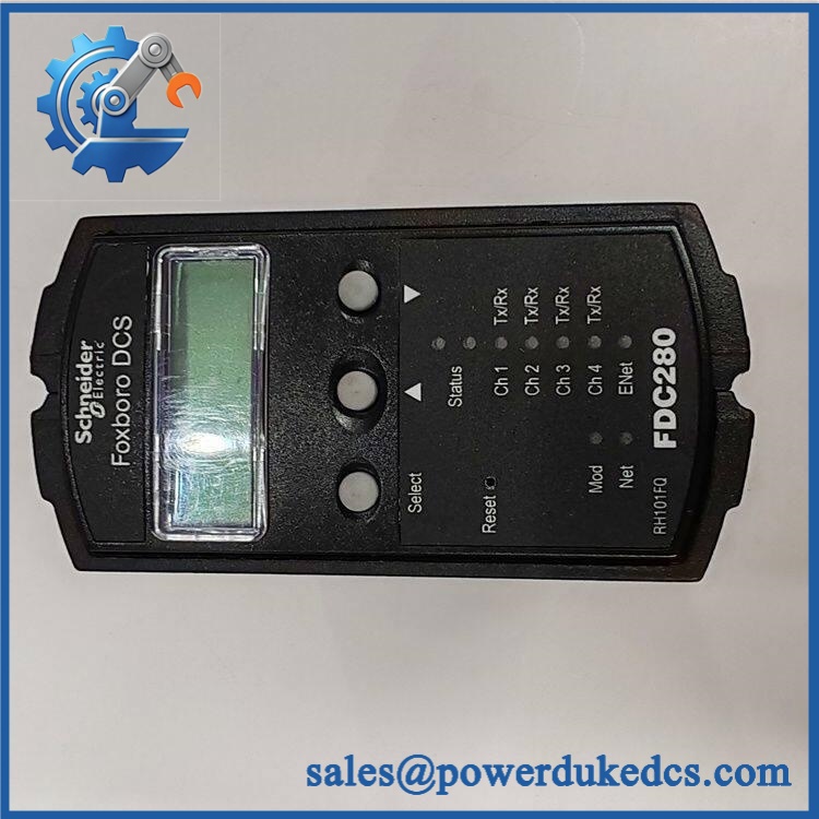
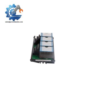
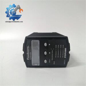
FOXBORO FDC280 RH101FQ
Module 5: Migration, Compatibility & Installation Traps
Replacement Matrix
| Replacement Type | Assessment |
|---|---|
| Drop-in Replacement | Conditional — appropriate for an exact RH101FQ replacement when the baseplate, network adapters, software environment, and control configuration match |
| Software Compatible | Conditional — Foxboro DCS Control Core Services v9.3 or later is required; installed drivers, image version, letterbug, and control database must also be compatible |
| Hardware Modification Required | Normally no for an exact RH101FQ replacement; baseplate, fiber/copper adapter, serial TA, and redundancy arrangement must be verified |
⚠️ Field Traps — Watch Out
1. Do not confuse with FCP280.
The official specification explicitly states that, unlike the Foxboro FCP280, the does not support the PIO bus. Its primary role is direct Ethernet and serial field-device integration. A migration from FCP280 therefore requires an architecture review rather than a simple module swap.
2. The baseplate and network adapters are part of the installation.
For the , the specified baseplate is RH101KF. The applicable network accessories include RH924WA for fiber and RH924UQ for copper, with revision requirements specified by Schneider Electric. Verify these components before removing the existing controller.
3. Software version matters.
Schneider specifies a host workstation running Foxboro DCS Control Core Services v9.3 or later. A hardware replacement that passes its local diagnostics can still fail at system commissioning if the control image, driver set, or configuration database is not compatible.
4. Serial port configuration must be preserved.
Each of the four serial ports can be configured independently as RS-232, RS-422, or RS-485. Photograph the existing port assignments and termination assemblies before replacement. An electrically incorrect serial standard can leave the controller healthy while the field devices remain unreachable.
Module 6: Quality Assurance SOP
- OEM anti-counterfeit visual inspection — inspect FOXBORO identification, RH101FQ marking, enclosure, LCD/buttons, connectors, PCB condition, and visible manufacturing information.
- Exact part-number verification — confirm against the purchase order and physical label. Schneider Electric’s current specification lists .
- Baseplate compatibility check — verify the intended installation uses the specified RH101KF baseplate and that its slot configuration matches simplex or fault-tolerant service.
- Mechanical inspection — examine mounting lugs, housing, connectors, display area, button assembly, and mating interfaces for damage or contamination.
- Power-up self-test (POST) — energize the controller using a controlled 24 VDC test source. Record startup behavior, diagnostic indications, current consumption, and abnormal temperature rise. Schneider specifies self-checking at power-up and run-time diagnostics during operation.
- Control-core and I/O-core diagnostic verification — confirm that the controller completes startup diagnostics and establishes normal operating status before connecting field networks.
- Ethernet interface verification — test the appropriate copper or fiber network path using the installed adapter configuration. For copper connections, Schneider specifies 1000Base-T Cat 5 cabling with a maximum switch-to-controller distance of 100 m; the specified fiber arrangement supports up to 2 km under the documented conditions.
- Serial interface verification — test representative ports in the required RS-232, RS-422, and/or RS-485 modes. For RS-485 applications, verify correct termination and multidrop behavior before connecting the complete device network.
- Communication handshake verification — validate the actual deployed protocol, such as Modbus TCP, Modbus RTU, EtherNet/IP, PROFINET, or OPC UA, using the corresponding Foxboro driver and test device. The current specification lists these supported driver families explicitly.
- Control-function verification — where an approved test environment is available, load the applicable control database and verify regulatory, logic, timing, sequential-control, and alarm functions.
- Fault-tolerant verification where required — for redundant service, pair two compatible modules on the dedicated baseplate and confirm synchronization, message comparison, and failover behavior. Schneider specifies less than 0.5 seconds to marry fault-tolerant modules.
- Final QC and packaging — record module part number, hardware/software revision, diagnostic results, network-adapter configuration, serial-interface configuration, photographs, ESD protection, and packaging condition before shipment.
Engineering note: The supplied FOXBORO identification is strongly supported by current Schneider Electric documentation: is the specified module part number. The controller is rated for 24 VDC typical input, 8.5 W maximum consumption per non-redundant module, −20 to +60°C operating temperature, and 0.8 kg maximum module weight.



 Start Chat


