

Description
- Brand: GE General Electric
- Full Model Number: IS200AEADH4ADA
- Lifecycle Status: Obsolete / Legacy
- Core Function: Mark VI AEAD analog input terminal/interface board
- Top 3 Technical Specs: AEAD functional group; H4 hardware group; 3 × 12-pin terminal strips
- System: GE Mark VI Speedtronic Turbine Control
- Application: Gas turbine, steam turbine, and BOP control
- Board Construction: Rectangular PCB assembly; no dedicated front panel
- Physical Features: Multiple plug-in connectors; screw/terminal interfaces; two heatsink assemblies; eight relays
- Stock & Condition: Exact stock confirmation required; New Surplus / Tested Refurbished; Emergency shipping subject to warehouse cutoff
Available technical references consistently identify the IS200AEADH4ADA as a GE Mark VI board assembly and describe the AEAD functional abbreviation, H4 hardware group, and multiple field-terminal/connectors. Some current reseller listings disagree on the exact signal-channel description, so the full assembly number and terminal-board application should be verified against the site’s GE drawings before substitution.
Module 3: Obsolescence & Supply Chain Deep Dive
A failed IS200AEADH4ADA can create a field-signal problem inside a legacy Mark VI turbine control system without justifying replacement of the complete controller architecture. The board belongs to GE’s Mark VI Speedtronic platform, where terminal/interface boards provide the physical connection between field wiring and the control electronics. Its documented construction includes three 12-pin terminal strips, several plug-in connectors, relays, capacitors, resistors, and heatsink assemblies.
The TCO case is therefore centered on preserving installed infrastructure. A matched board replacement can avoid cabinet redesign, field rewiring, control-logic migration, and the commissioning effort associated with a platform-wide upgrade. However, this part should not be approved from the marketing description alone: current secondary sources conflict over whether the H4A assembly should be characterized as an analog input terminal board, AIO board, or another interface assembly. The safest procurement practice is to match the complete IS200AEADH4ADA identification and physical terminal layout to the installed GE documentation.
Module 4: Compatibility & Replacement Matrix
| Approval Item | Engineering Assessment |
|---|---|
| Exact Part Replacement | Drop-in Replacement when the existing assembly is identified as IS200AEADH4ADA |
| Software Compatibility | Normally configuration-dependent rather than firmware-driven; verify the connected Mark VI application |
| Hardware Modification | Normally none for an exact hardware match |
| Board-Level Substitution | Not recommended without engineering verification |
| Estimated Physical Swap | 1–3 hours for qualified turbine controls personnel |
| Estimated Engineering Cost | 250–1,250 planning allowance |
| Commissioning Requirement | Required for field-signal verification before returning the turbine to normal service |
⚠️ Field Traps — Watch Out
- Functional-description conflict: Several current listings describe this part differently, including analog-input terminal board and AIO terminology. Do not approve a replacement based solely on a generic “analog input” description. Match the GE board number, terminal arrangement, connector locations, and cabinet drawing.
- Revision suffix matters: IS200AEADH4ADA should not automatically be treated as interchangeable with every IS200AEADH4A variant. Record the complete suffix and inspect the installed board before ordering.
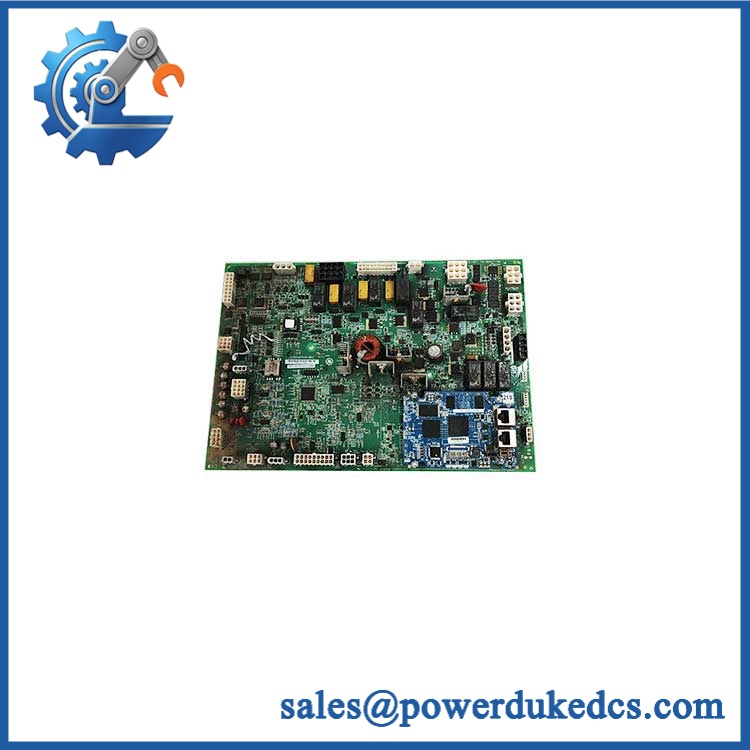
GE IS200AEADH4ADA
Module 5: Quality Assurance & Testing SOP
- OEM anti-counterfeit visual inspection — verify GE markings, board identification, functional designation, hardware group, PCB construction, component placement, and manufacturing labels.
- Full part-number verification — record exactly, including every suffix character.
- Physical-layout inspection — verify the three 12-pin terminal strips, connector arrangement, mounting holes, heatsinks, relays, and terminal hardware against the approved reference unit.
- PCB condition inspection — check for corrosion, contamination, cracked solder joints, damaged traces, overheated components, bent connector contacts, and unauthorized repair work.
- Electrical pre-screening — perform continuity, resistance, grounding, and isolation checks before applying power.
- Power-on self-test (POST) — install the board in an appropriate GE Mark VI test environment and confirm expected system initialization and diagnostic status.
- Terminal-channel verification — stimulate applicable field-input channels with calibrated test signals and verify expected values at the receiving control interface.
- Relay/output-path testing — exercise applicable relay contacts and verify continuity, pickup/release behavior, and abnormal-contact conditions.
- Signal integrity testing — check representative analog signals for scaling errors, open circuits, unstable readings, and unintended cross-channel interaction.
- Extended energized test — monitor the board for intermittent faults, abnormal temperature rise, relay instability, and signal drift.
- Final QC release — photograph the identification label, retain the complete test record, package with ESD protection, and preserve serial/part-number traceability.
Because published secondary references do not agree on every functional specification for this exact board, the acceptance test should be based on the installed Mark VI drawing and approved board documentation, not on a generic reseller specification sheet.
Module 6: Procurement & Lifecycle FAQ
Q1. Is genuinely in stock, and what is the cutoff for emergency shipping?
Exact stock must be confirmed by full part number and suffix before the PO is released. For emergency requirements, provide the quantity and destination early enough to confirm tested inventory and the available carrier cutoff.
Q2. How do you verify the condition and authenticity of an obsolete ?
The unit should undergo OEM-marking inspection, complete part-number verification, PCB and connector examination, electrical screening, energized testing, and applicable signal/relay functional testing. Identification photographs and the QC record should remain linked to the shipped unit.
Q3. Are there firmware compatibility issues engineers should check before issuing the PO?
The greater concern is hardware and application compatibility. Verify the Mark VI rack location, connected terminal wiring, board revision, signal assignments, and control-system configuration. Firmware should not be assumed irrelevant merely because this is a board-level component.
Q4. Can an IS200AEADH4A be substituted for ?
Not automatically. The base designation is similar, but the complete ADA suffix should be matched against the installed hardware and drawings. Current listings also differ in their descriptions of the board’s exact I/O function, which makes physical and documentation-level verification essential.
Q5. What warranty and return terms should procurement require?
Require a written warranty period, DOA criteria, return-authorization procedure, serial-number traceability, and exclusions for incorrect wiring, field modification, and installation-related damage. For an obsolete Mark VI board, the exact hardware identification should appear on both the quotation and warranty documentation.











 Start Chat


