

Description
- Model & Brand: IS200VTCCH1CBB | GE General Electric
- Series: Mark VI Speedtronic
- Part Type: Thermocouple Input Terminal Board / VTCC board
- Functional Acronym: VTCC
- Input Capacity: 24 thermocouple channels
- Supported Thermocouple Types: E, J, K, S, T
- mV Input Range: -8 to +45 mV
- Physical Dimensions: Approx. 330 × 102 mm (13.0 × 4.0 in) for the terminal-board installation envelope; exact board depth depends on the mounting and connector arrangement.
- Estimated Net Weight: Approx. 0.5 kg
- Estimated Shipping Weight: Approx. 0.9–1.3 kg with ESD shielding and rigid packaging
- What’s in the Box: IS200VTCCH1CBB board; ESD shielding protection; protective packaging; mating terminal board, cable, and mounting hardware only when specifically included
- Compatible Termination: TBTC or DTTC terminal-board arrangement
- Cold-Junction Compensation: Two cold-junction reference locations
- Front Indicators: RUN, FAIL, STATUS LEDs
The Mark VI system guide identifies VTCC as the thermocouple input processor and specifies 24 channels, while current part records identify IS200VTCCH1CBB as the conformal-coated C-revision VTCC board.
Product Introduction
Inside the Mark VI cabinet, the VTCC forms the measurement path between thermocouple termination hardware and the VME-based control system. GE IS200VTCCH1CBB is a Mark VI Thermocouple Input Board that receives temperature signals from up to 24 thermocouples through compatible termination boards such as TBTC or DTTC. The board supports E, J, K, S, and T thermocouples and mV inputs over -8 to +45 mV. Two cold-junction reference locations provide the basis for cold-junction compensation.
The C-revision VTCC uses a conformal-coated PCB, and the board includes parallel and serial front-panel interfaces together with RUN, FAIL, and STATUS indicators. GE’s Mark VI documentation describes automatic calibration using filtered calibration references and zero voltages, plus hardware and software limit checking. For legacy turbine inventory, exact revision and termination-board pairing should be retained in the spare-parts record (a VTCC with a different input range is not automatically equivalent).
Core Technical Specifications
| Parameter | Value |
|---|---|
| Manufacturer | General Electric |
| Full Part Number | IS200VTCCH1CBB |
| Series | Mark VI Speedtronic |
| Functional Acronym | VTCC |
| Product Type | Thermocouple Input Board |
| Primary Function | Temperature signal acquisition |
| Number of Inputs | 24 |
| Thermocouple Types | E, J, K, S, T |
| mV Input Span | -8 mV to +45 mV |
| Termination Options | TBTC or DTTC |
| Cold-Junction Compensation | 2 reference locations |
| ADC Resolution | 16-bit A/D, better than 14-bit effective resolution |
| Measurement Accuracy | Approximately 53 µV, excluding cold-junction reading |
| Cold-Junction Accuracy | Approximately 2 °F |
| Maximum Software Conformity Error | Approximately 0.25 °F |
| AC Common-Mode Rejection | 110 dB at 50/60 Hz for balanced impedance |
| Common-Mode Voltage | ±5 V |
| Normal-Mode Rejection | 80 dB at 50/60 Hz for 250 mV RMS |
| Sampling Rate | 120 samples/s at 60 Hz; 100 samples/s at 50 Hz |
| Fault Detection | High/low hardware and software limit checking |
| Front LEDs | RUN, FAIL, STATUS |
| PCB Coating | Conformal coating |
| Front Connectors | Parallel and serial interfaces |
| Board Revision | C functional revision; BB assembly identifier |
| Approx. Board Size | Approx. 13 × 4 in / 330 × 102 mm installation envelope |
| Reported Weight | Approx. 0.5 kg |
| Lifecycle | Legacy Mark VI spare |
| Firmware | Board-specific processing; verify installed system revision |
GE’s Mark VI system guide gives the principal VTCC electrical characteristics, while current technical records identify the exact IS200VTCCH1CBB configuration as a C-revision, conformal-coated VTCC board.
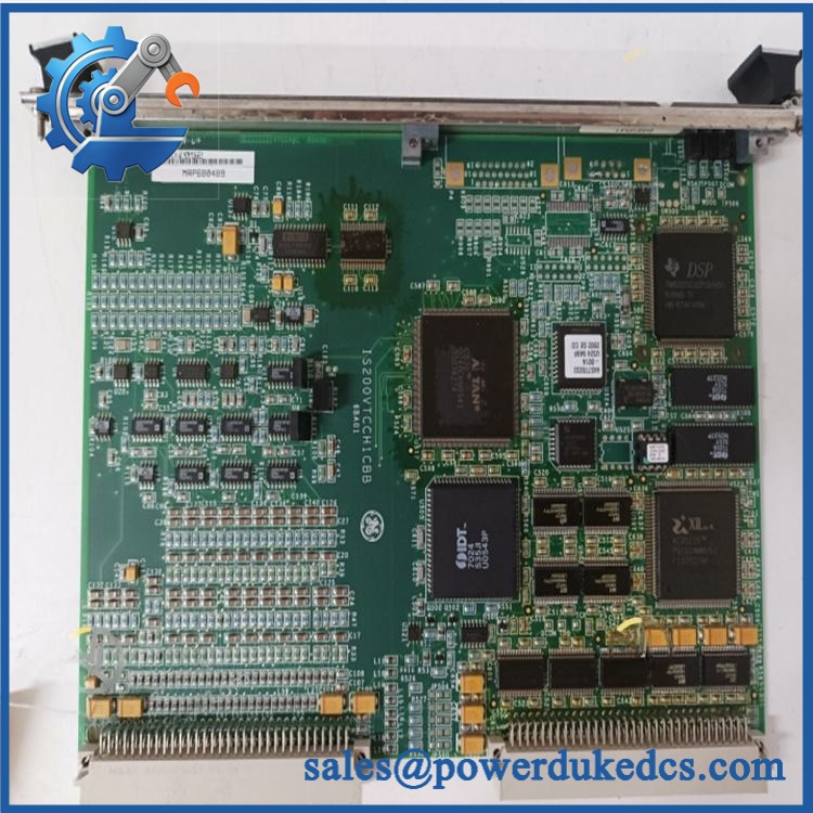
GE IS200VTCCH1CBB
🚨 Global Compliance & Industry Certifications
is an internal turbine-control component. Certification should therefore be established against the actual Mark VI system, terminal-board configuration, cabinet, and installation environment.
- CE Mark: No standalone CE declaration specific to was established from the records reviewed.
- UL/cUL: No exact-board UL/cUL listing was established from the reviewed technical records.
- ATEX/IECEx: No standalone ATEX or IECEx certificate was established for this exact VTCC board.
- Marine Approvals: No specific DNV, ABS, or Lloyd’s Register approval was established.
- EMC: The Mark VI system architecture incorporates grounding, shielding, filtering, and cabinet-level EMC controls; thermocouple wiring quality directly affects measurement integrity.
- System-Level Compliance: The complete Mark VI installation determines applicable regulatory status.
A CE or hazardous-area claim associated with another Mark VI component should not be copied into the asset record for this board. Verify specific lot certifications with OEM.
🚨 Long-Term Storage & Asset Preservation Guide
Keep in an ESD shielding bag. The conformal coating provides additional environmental protection, but it does not eliminate ESD or connector contamination risks.
Control warehouse humidity. A practical long-term target is below 60% RH, with no condensation cycles. Thermocouple electronics are sensitive to leakage paths and contact contamination, particularly around low-level millivolt measurement circuits.
Protect the front and backplane connectors. Do not place the board directly against metal shelving or let heavy equipment rest on the connector assemblies. One damaged contact can produce a thermocouple channel fault that resembles a sensor problem.
Keep the cold-junction reference area clean. Avoid touching or contaminating the components associated with cold-junction compensation. Temperature measurement accuracy depends on these reference measurements.
Photograph the installed configuration before storage. Record the full part number, revision, connector locations, termination-board type, and any visible configuration information. This preserves traceability without requiring the ESD packaging to be opened later.
Do not prescribe a generic capacitor-reforming schedule. No specific reforming interval was established for this VTCC revision. Controlled bench verification is preferable before releasing a long-stored board to a turbine.
Physical Installation Prerequisites
is a Mark VI VME thermocouple input board, not a standalone DIN-rail module. The field thermocouples terminate on a compatible TBTC or DTTC board, with cabling connecting that termination hardware to the VTCC board.
Before installation:
- Confirm the host system is a GE Mark VI turbine-control system.
- Verify the complete identification and revision.
- Confirm whether the installation uses TBTC or DTTC termination.
- Label all thermocouple cables before disconnecting the existing board.
- Inspect VME/backplane connectors for bent, recessed, oxidized, or contaminated contacts.
- Verify the two cold-junction reference assemblies remain physically intact.
- Keep thermocouple extension wiring separated from high-current conductors where cabinet routing permits.
- Preserve the original shield and grounding arrangement.
- Verify thermocouple polarity and type for every channel before commissioning.
- Check that the installed sensor type is one of E, J, K, S, or T.
- Do not connect unsupported B, N, or R thermocouple types to this configuration; GE documentation indicates a different VTCC configuration is required for those ranges.
- Verify the mV signal remains within the documented -8 to +45 mV range.
- Do not impose a generic 50 mm clearance around the PCB; use the Mark VI cabinet’s actual rack and airflow arrangement.
- Use ESD controls throughout handling.
- Perform point-to-point continuity and polarity checks before restoring the temperature channels.
- Complete representative thermocouple simulation and cold-junction verification before returning the turbine to service.
Buyer’s FAQ
Q1. What HS tariff code should be used for GE ?
A: Final classification depends on the importing country’s tariff schedule and the customs description. As a dedicated printed-circuit component for industrial temperature measurement and control, HS heading 8538 or 9031 may be considered depending on how the importing authority classifies the board’s principal function. The importer or customs broker should confirm the final national tariff code.
Q2. Does Country of Origin equal the location from which the VTCC board is shipped?
A: No. COO concerns the applicable origin rules for the physical board, not the export warehouse. Current industrial records identify the United States as the origin for some listings, but the actual unit’s traceability documentation should control the customs declaration.
Q3. How should I package and insure for international shipment?
A: Place the board in an ESD shielding bag, protect the VME connector and front connectors with rigid cushioning, immobilize the board inside a rigid carton, and add moisture protection appropriate to the shipping route. Supplier records report approximately 0.5 kg for the board, but actual packed weight should be measured before freight booking. For a turbine-critical spare, insurance should cover the full declared replacement value.
Q4. Does include the latest firmware pre-loaded?
A: Do not assume that a stored VTCC carries the latest system software revision. The board performs thermocouple signal acquisition and diagnostics within the Mark VI VME architecture; system software and configuration reside elsewhere in the control system. Before commissioning, verify the board revision, termination-board type, sensor configuration, and host Mark VI software environment.
A: Do not treat it as a routine live-service operation. The VTCC interfaces with multiple thermocouple circuits and the Mark VI VME backplane. Follow the site’s approved Mark VI isolation procedure, protect the board against ESD, document every cable position, then verify thermocouple type, polarity, cold-junction behavior, and representative temperature readings before returning the channels to service.











 Start Chat


