

Description
- Brand: GE Multilin
- Full Model Number: UR8AH
- System/Series Family: Multilin Universal Relay Series
- Core Function: Analog CT/VT acquisition module for current and voltage measurement within a UR protection relay
- Top 3 Hardcore Specs: 3 phase CT inputs | 1 ground CT input | 4 VT inputs
- CT Rating: 1 A / 5 A
- VT Inputs: 4 channels
- Configuration: 4 CT / 4 VT class architecture
- Software: EnerVista UR
- Firmware Compatibility: 3.5x or earlier reported for legacy CPU configurations
- Stock Status: New Surplus — exact hardware revision and packaging condition to be verified before shipment
Technical Product Introduction
A CT/VT acquisition failure can compromise the measurements used by a protection relay for current, voltage, power, frequency, and fault calculations. The GE UR8AH is an analog measurement module for the Multilin Universal Relay platform. Its commonly documented configuration provides three 1 A/5 A phase CT inputs, one 1 A/5 A ground CT input, and four VT inputs, creating the measurement interface between instrument transformers and the relay’s processing system.
Compatibility deserves particular attention with this legacy module. Available technical references identify the UR8AH with older UR CPU configurations and report firmware 3.5x or earlier as the applicable compatibility range. Physical specifications reported by suppliers are approximately 150 × 180 × 40 mm, although dimensions and weight should be confirmed against the actual revision before shipment. Do not substitute a newer CT/VT module solely because its connector arrangement appears similar. The host relay’s hardware configuration and firmware must be checked first.
Application Scenarios & Field Realities
- For legacy substation feeder protection, the UR8AH provides the relay with phase-current, ground-current, and voltage measurements needed by the host protection scheme. CT secondary wiring must match the relay’s configured 1 A or 5 A input selection.
- Where ground-fault measurement is critical, the dedicated ground CT channel provides a separate measurement path in addition to the three phase CT channels. Verify whether the existing installation uses a dedicated ground CT or another residual-current arrangement before transferring wiring.
- Inside industrial distribution panels, four VT channels allow the host UR relay to acquire voltage information alongside current measurements. This matters when the relay configuration uses voltage-dependent protection, metering, or power calculations.
- During maintenance of older UR installations, the firmware relationship becomes a practical constraint. References identify the UR8AH with legacy CPU modules such as UR-9A, UR-9C, and UR-9D and firmware versions 3.5x or earlier. Confirm the installed CPU and firmware before ordering a replacement.
Migration, Compatibility & Installation Traps
Replacement Matrix
| Replacement Condition | Assessment | Engineering Requirement |
|---|---|---|
| Existing hardware is UR8AH with matching revision and host CPU | Drop-in Hardware Replacement | Verify connector layout, CT/VT configuration, CPU compatibility, and firmware |
| Same configuration but replacement hardware revision differs | Software Compatible — verification required | Confirm host relay recognizes the module and retains the intended CT/VT configuration |
| Replacing with a different UR CT/VT module | Hardware Compatibility Review Required | Compare CT count, VT count, ratings, connector assignment, and firmware support |
| Replacing with a module having different CT secondary characteristics | Hardware Modification Required | Reconfigure CT settings and verify protection calculations before energization |
Field Traps — Watch Out
CT secondary mismatch is a serious installation issue. The is documented with 1 A/5 A CT inputs. The installed CT secondary rating must correspond to the relay configuration. Never assume that a physically compatible connector means the protection settings are correct.
Firmware and CPU compatibility can stop an otherwise correct replacement. Legacy references associate with older CPU configurations and firmware 3.5x or earlier. Record the existing CPU model and firmware before removing the original module.
Never open-circuit an energized CT secondary. During replacement work, follow the site’s approved CT isolation and shorting procedure. The CT circuit must be handled by qualified protection personnel.
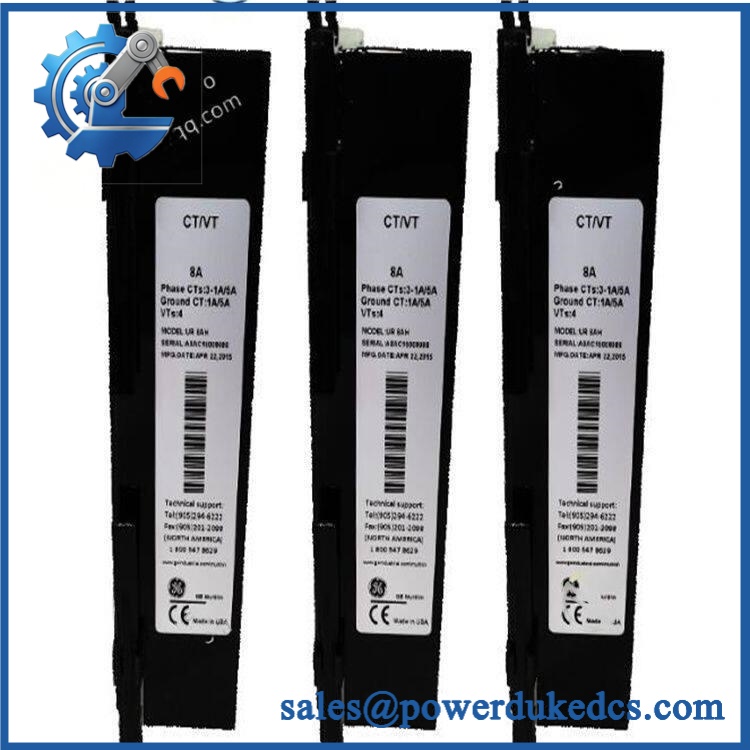
GE UR8AH
Quality Assurance SOP
Before shipment, each available unit should pass a documented inspection sequence:
- OEM anti-counterfeit visual inspection — Verify GE/Multilin markings, identification, labels, connectors, PCB construction, and visible manufacturing identifiers.
- Configuration verification — Confirm the unit corresponds to the expected architecture: 3 phase CT inputs, 1 ground CT input, and 4 VT inputs.
- CT input inspection — Check all CT terminals and associated circuitry for oxidation, loose hardware, contamination, overheating marks, or physical damage.
- VT input inspection — Examine all voltage-input terminals and insulation areas for damage or evidence of arcing.
- PCB and connector inspection — Inspect connector pins, solder joints, board surfaces, mounting points, and protective components under suitable lighting and magnification.
- Host-relay recognition test — Install the module in a compatible UR test platform and verify that the host relay recognizes the CT/VT hardware without configuration or hardware faults.
- CT channel verification — Using an appropriate protected test source, verify each phase and ground CT channel independently at the configured secondary rating.
- VT channel verification — Apply controlled test voltage to each VT input and confirm that the host relay reports the expected channel response.
- Configuration verification — Confirm CT ratio, CT secondary selection, VT ratio, phase assignment, and ground-current assignment against the customer’s original configuration.
- Firmware compatibility check — Record the tested host CPU and firmware revision, particularly for legacy installations associated with firmware 3.5x or earlier.
- Final documentation — Record the actual model, hardware revision, test results, physical condition, and packaging condition. Photograph the nameplate and connector interfaces before packing.
- Shipment release — Any discrepancy between the physical module and the ordered configuration stops shipment until the discrepancy is resolved.











 Start Chat


