

Description
- Brand: HIMA
- Full Model Number: K1406
- System/Series Family: H41q / H51q
- Core Function: 19-inch rack for installing HIMA safety-system I/O modules and associated coupling and power-distribution hardware
- Top 3 Hardcore Specs: 21 slots; 4 SU rack height; 19-inch construction
- I/O Slots: Slots 1–16 reserved for I/O modules
- Coupling Slot: Slot 17 for F7553
- Power Distribution Slots: Slots 18–21 for up to 4 F7133 modules
- Associated Kit: B9302
- Cable Interface: BV7032 flat cable; standard B9302 lengths include 0.5 m and 1 m
- Stock Status: New Surplus or Fully Tested Refurbished; exact rack configuration to be confirmed
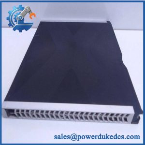
HIMA K1406 is documented as a 4-unit-high, 19-inch central I/O subrack for H41q/H51q systems. In the B9302 assembly kit, it is paired with an F7553 coupling module and BV7032 flat cable.
Module 3: Technical Product Introduction
When an H41q or H51q cabinet has to remain in service, the rack itself can become the limiting spare. K1406 is not a CPU or I/O electronics module; it is the 19-inch I/O subrack that physically organizes the safety-system modules and their associated bus and power-distribution connections. HIMA documentation referenced for the B9302 assembly describes K1406 as a 4 SU, 19-inch rack with an integrated cable tray and hinged label receptacle. Slots 1 through 16 are assigned to I/O modules, while slot 17 accommodates the F7553 coupling module.
Its value becomes clearer during cabinet refurbishment. The K1406 architecture provides dedicated positions for the main I/O population plus optional F7133 four-channel fused power-distribution modules in slots 18–21. The associated B9302 kit can use BV7032 flat cable in standard 0.5 m or 1 m configurations, with the source documentation stating that the total bus-cable length can reach up to 30 m. In practice, cable length, slot assignment, coupling hardware, and power-distribution configuration must be treated as one assembly rather than four unrelated spare parts.
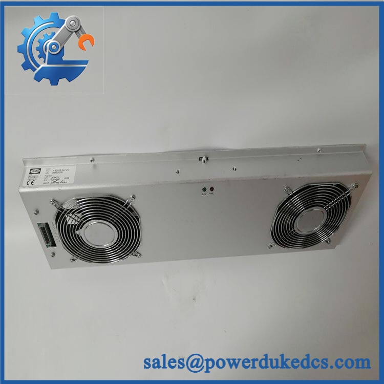
HIMA K1406
Module 4: Application Scenarios & Field Realities
- During an H41q or H51q cabinet rebuild, K1406 provides the physical 19-inch rack structure for the I/O population. The first 16 slots are intended for I/O modules, so the rack layout should be checked against the existing system drawing before any module relocation.
- Where the B9302 assembly is used, slot 17 is assigned to the F7553 coupling module and the BV7032 flat cable provides the associated bus connection. Cable length is order-dependent, with documented standard configurations of 0.5 m and 1 m.
- For cabinets requiring protected I/O power distribution, slots 18–21 can accommodate one to four F7133 modules. Each F7133 provides four-channel fused power distribution, so the actual rack population can vary depending on the cabinet design.
- When troubleshooting intermittent I/O communication after a rack replacement, inspect the mechanical seating of the rack, coupling module, and bus cable before blaming individual I/O cards. A physically correct with the wrong associated cable length or an incorrectly seated F7553 can create system-level symptoms even though every electronic module tests normally.
Module 5: Migration, Compatibility & Installation Traps
Replacement Matrix
Replacement classification: Drop-in Replacement for an existing installation when the rack type, slot arrangement, backplane interfaces, associated F7553 coupling module, and cable configuration remain unchanged.
Software compatibility: Not applicable to the rack itself. is a passive mechanical and electrical rack assembly rather than a programmable controller. Software compatibility is determined by the I/O, coupling, and central-system modules installed in the rack.
Cross-model replacement: Hardware modification required unless explicitly documented as equivalent. Another 19-inch HIMA rack may have different slot assignments, power-distribution provisions, coupling arrangements, or mechanical interfaces. Matching rack width alone is not sufficient.
Field Traps — Watch Out
1. Slot allocation is not arbitrary. The documented arrangement reserves slots 1–16 for I/O modules, slot 17 for , and slots 18–21 for optional F7133 power-distribution modules. Repositioning hardware without checking the system documentation can create wiring and bus-connection errors.
2. Verify the complete assembly, not only the rack. The kit combines , , and BV7032 cable hardware. Standard cable lengths include -0.5 and -1, while other lengths can be ordered as -X. Substituting the wrong cable can affect the physical installation even when the rack itself is correct.
3. Check the bus-length budget. The referenced HIMA documentation gives a maximum total bus-cable length of 30 m for the arrangement. A cabinet expansion that ignores the cumulative cable length can exceed the documented architecture.
Module 6: Quality Assurance SOP
Pre-Shipment Inspection Protocol for HIMA
- OEM identity inspection: Verify HIMA marking, exact designation, rack identification, hardware markings, and associated assembly information where available.
- Mechanical inspection: Examine the 19-inch frame, 4 SU structure, mounting flanges, backplane interface, integrated cable tray, hinged label receptacle, and retaining hardware for deformation, cracks, corrosion, or unauthorized modification.
- Slot inspection: Check all 21 module positions for mechanical obstruction, damaged guides, bent contacts, contamination, or foreign material.
- Backplane inspection: Examine accessible electrical interfaces for oxidation, contamination, bent contacts, loose hardware, and signs of overheating.
- Coupling-interface verification: Confirm the slot-17 interface is mechanically compatible with the coupling module used in the intended assembly.
- Power-distribution verification: Where slots 18–21 are populated, inspect the interfaces intended for F7133 four-channel fused power-distribution modules.
- Cable-path inspection: Check the integrated cable tray and associated mounting points for damage that could interfere with BV7032 routing.
- Flat-cable continuity test: For a supplied assembly, verify the cable for conductor continuity and unexpected shorts before installation.
- Mechanical fit test: Install representative HIMA modules into the rack to verify guide alignment, insertion depth, retention, and connector engagement.
- System-level bench verification: Where a suitable H41q/H51q test environment is available, install the intended coupling and I/O hardware and confirm correct rack-level communication before release.
- Final QC record: Record rack model, hardware identification, slot condition, backplane inspection result, associated cable configuration, test date, and inspector approval.
- ESD and mechanical packaging: Protect the rack connectors, guides, cable tray, and mounting hardware against impact, contamination, moisture, and electrostatic exposure during shipment.
Procurement note: should be purchased as a rack assembly matched to the existing H41q/H51q architecture, not simply as a generic 19-inch enclosure. The documentation establishes specific relationships between , , , and the optional modules; these relationships should be checked against the cabinet drawing before approving a replacement.



 Start Chat


