

Description
- Brand HIMA
- Full Model Number F3330
- System/Series Family H41q / H51q safety system
- Core Function 8-channel safety-related digital output switching for 24 VDC field loads
- Top 3 Hardcore Specs 8 output channels | 500 mA / 12 W per channel | SIL 3 safety-related design
- Stock Status New Surplus — confirm actual inventory condition and revision before shipment
Module 3: Technical Product Introduction
A failed digital output card can stop valves, contactors, solenoids, or other final control elements even when the processor itself remains healthy. HIMA F3330 is an 8-channel safety-related output module for H41q/H51q systems, providing 24 VDC outputs with up to 500 mA per channel. The module incorporates safe isolation and an integrated safety shutdown function; HIMA’s certified device list identifies F3330 as an 8-channel, 12 W safety-related output module.
At the channel level, the published electrical data is specific: maximum internal voltage drop is 2 V at 500 mA, permissible total line resistance is 11 Ω, undervoltage tripping occurs at or below 16 V, and the short-circuit operating point is approximately 0.75–1.5 A. The module also performs internal runtime checks, including output-signal readback and a walking-bit test for switching capability and cross-talk detection. Those diagnostics matter during maintenance because the card is doing more than simply energizing a 24 VDC load.
Module 4: Application Scenarios & Field Realities
- For final-element control in a safety shutdown cabinet, each F3330 channel can switch a 24 VDC load up to 500 mA, making the module suitable for discrete actuators and other field devices within the specified electrical limits. The safety shutdown behavior is built into the output architecture rather than delegated entirely to external circuitry.
- Where inductive loads such as solenoids are installed, pay close attention to the field wiring and suppression arrangement. The F3330 documentation specifies an external diode arrangement for inductive loads, so the actual load interface should be checked against the HIMA application documentation before commissioning.
- On H41q/H51q systems running safety-related output logic, the module’s internal test functions become important during fault diagnosis. Output readback and a walking-bit test can help identify switching-path problems that might otherwise be mistaken for a controller or field-device fault.
- During planned shutdown replacement, keep the exact hardware revision under control. HIMA’s revision list records valid F3330 revisions including revision 05 and revision 06 for the H41q/H51q family, so the installed system revision should be checked before substituting an older spare.
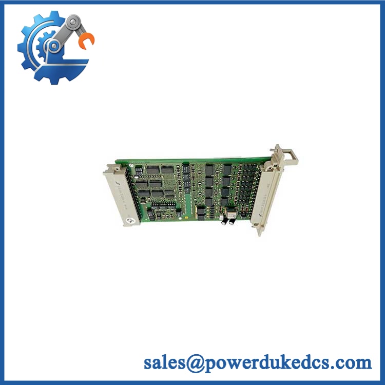
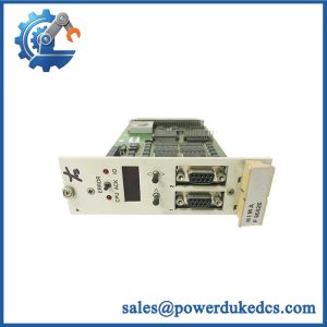
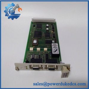
HIMA F3330
Module 5: Migration, Compatibility & Installation Traps
Replacement Matrix
| Replacement Status | Engineering Assessment |
|---|---|
| Drop-in Replacement | Yes, for a like-for-like replacement in a compatible H41q/H51q installation, subject to the installed hardware revision and approved system configuration. |
| Software Compatible | Generally yes for an exact-part replacement. No user application recompile is normally associated with replacing the same physical module, but the installed system’s approved hardware and firmware revision matrix must be respected. |
| Hardware Modification Required | Normally no for an exact replacement. Modification may be required when changing output-module types, load arrangements, terminal hardware, or system generation. |
⚠️ Field Traps: Watch Out
Load current is limited per output. The published rating is 500 mA / 12 W per channel. Do not treat the eight-channel module as an unrestricted 4 A supply. Each field circuit must remain within its own current, power, line-resistance, and load-type limits.
Inductive suppression must be checked before energizing the replacement. HIMA’s documentation specifies a diode arrangement for inductive loads. Omitting the required suppression or using an unsuitable component can increase switching stress and produce abnormal output behavior.
Watch the 16 V undervoltage threshold. A weak 24 VDC supply, excessive cable resistance, or a poor terminal connection can move the field voltage toward the module’s undervoltage-trip region. HIMA specifies a maximum permitted total line resistance of 11 Ω and undervoltage tripping at or below 16 V.
Confirm the hardware revision. HIMA’s H41q/H51q revision documentation lists revisions 05 and 06 as valid devices. An apparently identical spare still needs to be checked against the project’s approved hardware configuration.
Module 6: Quality Assurance SOP
Each surplus should be treated as a safety-related output assembly and tested accordingly before shipment.
- OEM anti-counterfeit visual inspection: Verify HIMA identification, exact designation, front labeling, connector arrangement, mechanical construction, and visible revision markings against controlled reference information.
- Part-number verification: Record the complete designation and available serial, revision, and manufacturing information.
- Mechanical inspection: Examine the housing, rack interface, front connector, retaining hardware, and accessible terminals for impact, corrosion, contamination, loose components, or unauthorized repair.
- Power-on self-test (POST): Energize the module using a controlled HIMA-compatible test arrangement and record the expected power and diagnostic behavior.
- Output-channel verification: Test all eight output channels individually using representative resistive loads within the rated 24 VDC / 500 mA operating envelope.
- Load-transfer test: Verify output voltage, current, and internal voltage drop under representative load conditions. The published maximum internal voltage drop is 2 V at 500 mA.
- Short-circuit protection check: Where the approved laboratory fixture permits, verify the output protection response using a controlled current-limited test rather than an uncontrolled hard short.
- Undervoltage verification: Confirm appropriate behavior as the controlled supply approaches the specified undervoltage threshold of 16 V.
- Output-signal readback verification: The documentation describes automatic runtime testing that reads back output signals; confirm the expected diagnostic response in the test fixture.
- Walking-bit test: Execute the documented switching test to verify channel operation and check for cross-talk between outputs. HIMA’s documentation identifies this as part of the module’s automatic testing routine.
- Communication handshake verification: Not applicable as a standalone network interface. Acceptance should instead verify correct interaction between the output module, HIMA processing system, diagnostic logic, and representative field loads.
- Safety diagnostic verification: Confirm that intentional test faults produce the expected diagnostic indication and that no unintended output remains energized after the relevant shutdown condition.
- Final QC record: Document revision, channel-by-channel measurements, diagnostic results, load conditions, visual inspection, traceability data, and packaging status.
Technical Identification Note: HIMA’s certification and revision documents identify as an 8-channel safety-related digital output module rated at 500 mA / 12 W per channel, with documented valid revisions for H41q/H51q systems. The associated HIMA data sheet also specifies automatic output readback and walking-bit testing, making functional verification a key part of a credible pre-shipment inspection.



 Start Chat


