

Description
- Brand: HIMA
- Full Model Number: F7133
- System/Series Family: H51 / H51q Extension Rack
- One-Sentence Core Function: Four-channel 24 VDC power distribution with individual fuse monitoring and LED fault indication
- Top 3 Hardcore Specs: 4 channels; max. 4 A slow-blow miniature fuse per channel; 4 TE rack space
- Stock Status: New Surplus / Factory Original — verify fuse configuration and revision before shipment
Module 3: Technical Product Introduction
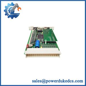
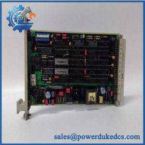
A blown distribution fuse should not take an entire safety-system cabinet into an unnecessary troubleshooting cycle. The HIMA F7133 is a four-fold power distribution module for H51 and H51q extension-rack applications. Each channel uses an individual miniature fuse for line protection, with associated LED indication and electronic fuse monitoring. HIMA’s own certification documentation identifies F7133 as a 4-fold power distribution module, while supplier technical data specifies a maximum 4 A slow-blow fuse per channel.
The architecture is useful during cabinet fault isolation because each protected circuit has its own indication path. Published technical descriptions state that the module distributes the L+ supply to the relevant I/O positions and provides rear 24 V supply connections for individual I/O slots. A relay contact changes state when a fuse is absent or faulty, allowing the distribution fault to be reported to higher-level monitoring. The module requires 4 TE of rack space, with published operating data of approximately 24 VDC / 60 mA for the module itself.
Module 4: Application Scenarios & Field Realities
- Inside an H51q extension rack, the F7133 is used where several 24 VDC circuits need individual protection rather than one common unfused feed. Its four-channel arrangement allows a failed branch to be isolated while the remaining protected circuits remain available.
- When an I/O position suddenly reports a supply-related fault, inspect the corresponding F7133 channel before replacing the I/O module itself. Each fuse is associated with an LED indication, while the evaluation logic monitors the fuse condition. That makes the distribution layer a useful first diagnostic point.
- During shutdown maintenance, verify the rear-terminal mapping against the cabinet drawing before moving conductors. The published design assigns rear contacts such as d6, d10, d14, and d18 to the 24 V supply paths for individual I/O slots. A physically correct replacement can still create a wiring fault if conductors are landed on the wrong positions.
- For safety-system fault annunciation, the relay-monitoring circuit is important. Technical documentation states that when all four fuses are healthy, the designated relay contact remains closed; when a fuse is missing or faulty, that contact opens. This can be tied into the system’s fault-reporting logic.
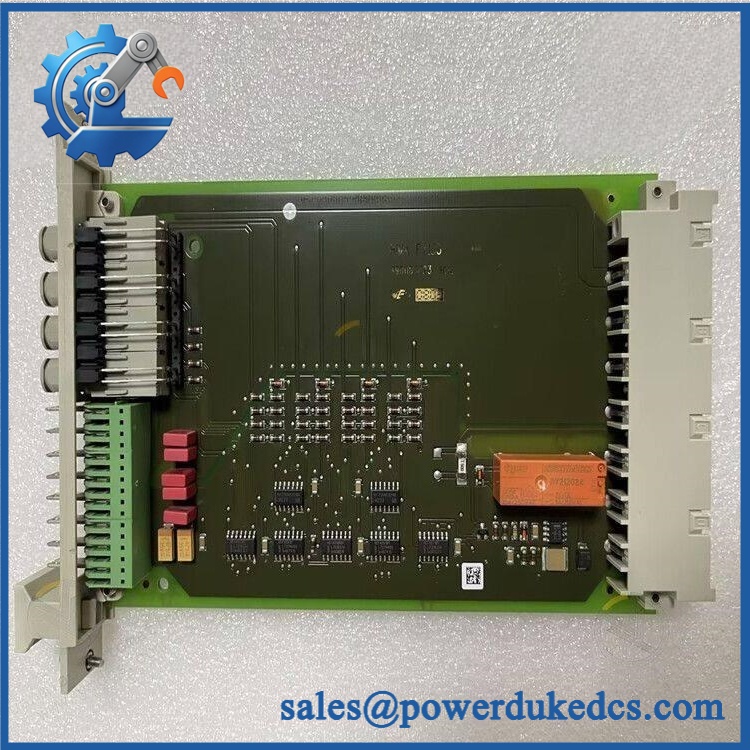
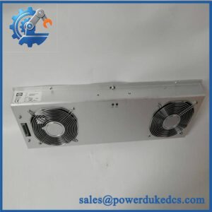
HIMA F7133
Module 5: Migration, Compatibility & Installation Traps
Replacement Matrix
| Replacement Type | Assessment |
|---|---|
| Drop-in Replacement | Yes, for a like-for-like F7133 in the compatible H51/H51q extension-rack arrangement |
| Software Compatible | Not applicable — the is a power-distribution and fuse-monitoring module |
| Hardware Modification Required | Normally no for an exact replacement, provided rack position, terminal mapping, fuse rating, and supply topology match |
⚠️ Field Traps — Watch Out
1. Fuse rating is not optional.
The documented configuration uses miniature fuses with a maximum rating of 4 A slow blow. Installing a higher-rated fuse defeats the intended branch protection and changes the fault behavior of the distribution circuit.
2. A dark LED does not automatically prove a fuse failure.
The published technical description notes that when the module is not wired, all LEDs are off. Loss of the incoming supply can also prevent the system from presenting meaningful individual fuse-status information. Confirm the supply and wiring state before diagnosing a channel from the LED alone.
3. Do not treat the rear-terminal arrangement as generic.
The module has defined rear connections for the individual 24 V supply paths. Photograph the original wiring and cross-check the HIMA rack drawing before removal, especially during a live turnaround where multiple adjacent channels may use similar conductor colors.
Module 6: Quality Assurance SOP
- OEM anti-counterfeit visual inspection — inspect HIMA markings, model label, front-panel legends, connectors, mounting hardware, and enclosure condition.
- Exact part-number verification — confirm against the purchase order, physical label, and inventory record.
- Mechanical inspection — verify the 4-TE form factor, connector condition, PCB/housing integrity, and front-panel fuse/LED area.
- Fuse configuration inspection — confirm all four fuse positions, ratings, physical condition, and correct slow-blow specification before energization. The published maximum is 4 A per channel.
- Power-on self-test (POST) — energize the module using a controlled 24 VDC test supply and inspect LED behavior, current draw, and abnormal heating.
- Channel continuity verification — check each protected power path individually from input through the associated fuse and distribution output.
- Fuse-monitoring verification — where the test fixture permits, simulate an approved fuse-open condition and verify the corresponding status indication and monitoring response.
- Relay-contact verification — verify the monitoring contact changes state correctly between a healthy four-fuse condition and an approved simulated fuse-fault condition. Published documentation identifies the healthy-state relay connection at d22/z24.
- Output-path verification — confirm the expected 24 VDC distribution at the applicable rear terminals under controlled load conditions.
- Communication handshake verification — not applicable as a standalone module test, because provides power distribution and fault monitoring rather than a network communication interface.
- Final QC and packaging — document the part number, fuse condition, LED status, electrical test results, inspection photographs, and packaging condition before shipment.
Engineering note: HIMA’s certification material explicitly identifies as a 4-fold power distribution device for the H51/H51q family, and HIMA’s certified equipment listing gives it a T4 classification.



 Start Chat


