

Description
- Brand: Motorola
- Full Model Number: MVME5500
- System/Series Family: MVME5500 Series VME64 Single-Board Computers
- One-Sentence Core Function: 1 GHz PowerPC VMEbus computer for embedded control, data acquisition, networking, and industrial computing
- Top 3 Hardcore Specs: 1 GHz MPC7455; 512 MB PC133 ECC SDRAM standard; VME64 with dual PMC expansion
- Stock Status: Stock condition, suffix, memory mezzanine, and installed PMC/IPMC configuration to be confirmed
Module 3: Technical Product Introduction
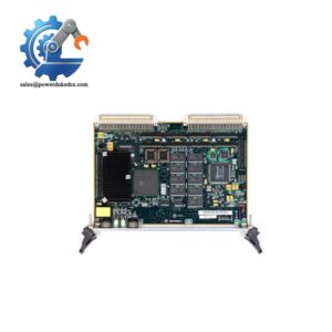
When a legacy VME computer fails, the replacement has to match far more than the processor. Backplane interfaces, VME address mapping, boot firmware, memory population, PMC hardware, and P2 I/O all affect whether the board can return to service without a cabinet redesign. The Motorola MVME5500 is a 6U VMEbus single-board computer built around a 1 GHz MPC7455 PowerPC processor and the Marvell Discovery GT-64260 system controller. Standard hardware provides 512 MB of 133 MHz PC133 ECC SDRAM, with expansion to 1 GB using the RAM5500 mezzanine module.
Its architecture is aimed at demanding embedded computing rather than simple I/O processing. The board supports VME64, two independent PCI buses, two 64-bit PMC sites, Gigabit Ethernet plus 10/100 Ethernet, two 16550-compatible asynchronous serial ports, on-board Flash, NVRAM, real-time clock, and watchdog functions. The processor has 32 KB instruction and 32 KB data L1 cache, 256 KB L2 cache, and 2 MB L3 cache. Motorola specified an operating range of 0°C to +55°C with forced-air cooling, so airflow through the VME chassis is part of the installation requirement—not an optional consideration.
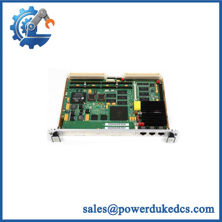
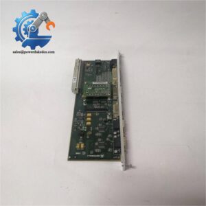
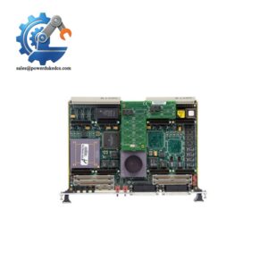
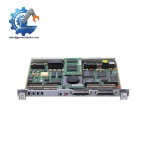
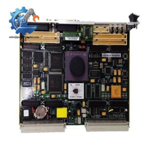
Motorola MVME5500
Module 4: Application Scenarios & Field Realities
- Inside a legacy VME control chassis, the MVME5500 can serve as the primary embedded computer handling application execution and VMEbus transactions. Before replacement, verify P1/P2 seating, the board’s VME system-controller setting, and the existing slot assignment. A board that powers up correctly can still fail system integration if its VME configuration does not match the chassis architecture.
- For systems with PMC-based interfaces, inspect both PMC positions before ordering. The board supports two IEEE P1386.1 PMC slots, including 33/66 MHz PCI operation, while a RAM5500 memory mezzanine occupies an area that can be physically covered when a PMC module is installed in PMC Slot 1. This is an important mechanical conflict during upgrades.
- On network-connected embedded controllers, the integrated Intel 82544EI provides 10/100/1000 Mb/s Ethernet, while a second interface supports 10/100 Mb/s operation. Check which Ethernet path the original application uses before changing software or transition modules; the two ports are not architecturally identical.
- During recovery of an aging VME installation, preserve the existing MOTLoad environment and VME settings before removing the original board. Motorola documents configurable VME inbound and outbound windows, master settings, address spaces, and CR/CSR parameters. Replacing hardware without recording those values can create a software or bus-mapping fault that initially looks like a defective replacement.
Module 5: Migration, Compatibility & Installation Traps
Replacement Matrix
Replacement Classification: Drop-in Hardware Replacement Within the Matching MVME5500 Configuration
A like-for-like MVME5500 replacement can normally be installed in an existing compatible VME chassis when the board suffix, front-panel style, memory configuration, PMC/IPMC population, P2 I/O arrangement, firmware environment, and VME settings match the original hardware. Motorola’s original ordering information identifies with Scanbe handles and with IEEE handles, so the short family designation is not sufficient for mechanical identification.
→ -0161 / -0163: Select the exact suffix based on the installed front-panel hardware. The -0161 and -0163 variants share the 1 GHz MPC7455 and 512 MB configuration, but their handle/front-panel implementations differ.
This is a hardware expansion rather than a simple software substitution. Motorola specifies the RAM5500 memory mezzanine for expansion to 1 GB. However, installing a PMC module in PMC Slot 1 can block the memory-mezzanine connector, so the expansion path must be reviewed together with the PMC configuration.
⚠️ Field Traps — Watch Out
1. Memory mezzanine versus PMC Slot 1 conflict: The RAM5500 expansion card cannot be used when a PMC module occupies PMC Slot 1 because the PMC mechanically covers the memory-mezzanine connector. Do not ship a replacement with a 1 GB expansion plan until the installed PMC arrangement has been checked.
2. VME configuration mismatch: MOTLoad manages many VME parameters, including inbound and outbound address windows and master configuration. Record the original vmeCfg settings before replacement and compare them after startup. Otherwise, the processor may boot normally while the application remains unable to communicate with other VMEbus masters or slaves.
3. Cooling requirement: Motorola specifies 0°C to +55°C inlet-air operating temperature with forced-air cooling, with approximately 400 LFM recommended at the upper temperature range. A board can pass a bench test and still become unstable inside a poorly ventilated VME enclosure.
Module 6: Quality Assurance SOP
The should be evaluated as an embedded computer system rather than as a conventional control card.
- OEM identification visual inspection: Verify Motorola markings, family designation, exact suffix, serial number, board revision, front-panel style, and major PCB identification labels.
- Processor verification: Confirm the MPC7455 1 GHz PowerPC processor configuration and inspect the heatsink, processor area, and surrounding components.
- Memory verification: Confirm the installed 512 MB ECC SDRAM population and identify any RAM5500 expansion hardware. Record the memory configuration detected during boot.
- Flash and NVRAM inspection: Verify the on-board Flash configuration, NVRAM condition, and battery-backed real-time-clock hardware where applicable.
- Mechanical inspection: Check P1/P2 VME connectors, PMC connectors, front-panel handles, ejector hardware, heatsink, board guides, and any transition-module interface.
- Power-on self-test (POST): Install the board in an approved VME test chassis and verify normal startup, processor initialization, memory detection, and diagnostic response.
- MOTLoad verification: Confirm access to the MOTLoad environment and record the firmware revision and key diagnostic output.
- VMEbus communication test: Verify VME master/slave transactions using an approved test fixture and confirm expected A16/A24/A32 and D32/D64 behavior for the configured application.
- Ethernet verification: Test the Gigabit Ethernet interface and the secondary 10/100 Ethernet interface independently, recording link and data-transfer results.
- Serial-port verification: Test both 16550-compatible asynchronous ports using an approved loopback or serial diagnostic setup.
- PMC verification: Where PMC hardware is supplied, verify correct PCI enumeration and data transfer. Record the exact installed PMC type and whether front or rear I/O is used.
- Watchdog verification: Test the watchdog timer under the authorized diagnostic procedure and confirm the expected reset or interrupt response. Motorola documents watchdog timeout as a reset-capable function.
- Thermal observation: Run an extended load test under controlled forced-air cooling and monitor board temperature, processor stability, Ethernet operation, and VME transactions.
- Final QC record: Retain part-number photographs, exact suffix, processor and memory identification, firmware revision, VME configuration, Ethernet results, serial-port results, PMC results where applicable, thermal observations, and final QC approval.
The is a full VMEbus computing platform with a 1 GHz MPC7455, 512 MB ECC SDRAM, 2 MB L3 cache, VME64 interface, dual PMC expansion, Gigabit Ethernet, serial interfaces, Flash, NVRAM, and watchdog support. For spare-part control, the exact suffix and installed expansion hardware matter just as much as the family name.



 Start Chat


