

Description
- Brand: TRICONEX
- Full Model Number: 3351S2
- System/Series Family: Triconex Tri-GP / Tricon General Purpose I/O
- Core Function: 32-channel TMR analog input acquisition for 0–5 VDC process signals
- Top 3 Hardcore Specs: 32 analog inputs; 0–5 VDC signal range; TMR architecture
- Stock Status: Verify current New Surplus, Factory Sealed, or Fully Tested Refurbished condition before order
Module 3: Technical Product Introduction
An analog-input failure can distort an entire set of process measurements when pressure, temperature, level, or other transmitter signals are concentrated on one I/O assembly. The TRICONEX 3351S2 is a 32-channel Tri-GP analog input module designed for 0–5 VDC signals in a TMR architecture. Triconex product documentation identifies 3351S2 as the standard analog-input module used with the 5351S2 Analog Input TriPak, whose corresponding baseplate is 2351S2. Lifecycle documentation likewise identifies 3351S2 as a 32-point, 0–5 VDC TMR analog-input module.
The key specification is signal density: 32 analog channels in one TMR input module. This is intended for voltage-transmitter applications rather than direct 4–20 mA acquisition. The Tri-GP product family also provides separate 3352S2/3354S2 variants for other analog-input requirements, including RTD/thermocouple/4–20 mA and HART-oriented applications. As a result, a replacement should be matched to the transmitter signal type and original baseplate assembly—not selected merely because another Triconex module also provides analog inputs.
Module 4: Application Scenarios & Field Realities
- In a Tri-GP cabinet receiving voltage-output transmitters, 3351S2 provides the 32-channel analog acquisition point for 0–5 VDC signals. Pressure, level, temperature-transmitter outputs, and other conditioned process measurements can be concentrated on the module without introducing a separate signal-conversion stage.
- For process measurements requiring TMR fault tolerance, the module participates in the Triconex redundant I/O architecture rather than functioning as an ordinary single-channel PLC analog card. The Tricon family uses triple-redundant architecture for critical processing and I/O, with diagnostics and voting used to maintain system integrity.
- During a brownfield replacement, the transmitter output range should be checked before the module is installed. A field device producing 4–20 mA is not a direct signal match for the 0–5 VDC 3351S2. Triconex provides other analog-input assemblies specifically for those signal types.
- When expanding a Tri-GP controller, the module should be evaluated together with its baseplate and overall I/O count. Product documentation identifies 3351S2 with the 2351S2 Analog Input Baseplate Kit; substituting a similar-looking baseplate without checking the complete assembly can create a field-termination mismatch.
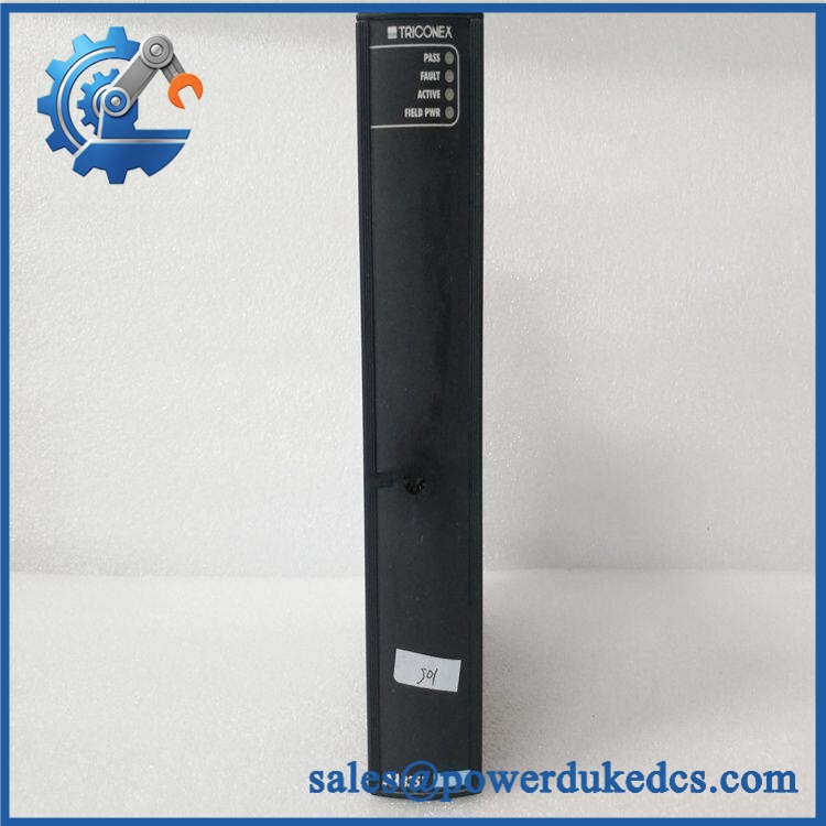
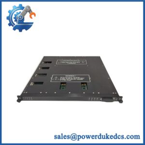
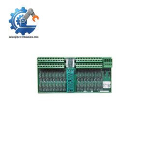
TRICONEX 3351S2
Module 5: Migration, Compatibility & Installation Traps
Replacement Matrix
Exact 3351S2 with matching Tri-GP configuration: Drop-in Replacement
When the installed controller uses 3351S2 with the corresponding approved baseplate, field termination, firmware, and project configuration, the module is normally a direct hardware replacement.
Different 33xx analog-input variant: Software Compatible / Hardware Verification Required
Other Triconex analog modules can differ in signal type, channel configuration, or special functions. Confirm the transmitter interface before substitution. The 3351S2 is specifically associated with 0–5 VDC analog inputs.
3351S2 replaced by 4–20 mA / RTD / thermocouple module: Hardware Modification Required
A different signal family requires the correct module and termination hardware. The transmitter wiring and application scaling must also be reviewed.
⚠️ Field Traps (Watch Out)
Signal-range trap: The 3351S2 is identified as a 0–5 VDC analog-input module. Installing it on a loop that actually produces 4–20 mA can produce incorrect values or an input-interface fault. Use the transmitter datasheet and cabinet drawings to establish the real field signal before replacement.
Baseplate mismatch: Triconex I/O modules use mechanically keyed assemblies designed to prevent installation into an incompatible configuration. Tricon documentation specifically states that I/O modules are mechanically keyed to their configured baseplates. Do not defeat the keying or force an apparently similar module into an unmatched assembly.
TMR wiring assumption: Do not treat 3351S2 as an ordinary single-channel analog card. Its TMR architecture means the complete module/baseplate/system arrangement must be maintained during migration, including the configured field termination and diagnostic scheme.
Module 6: Quality Assurance SOP
Pre-Shipment QA Protocol for TRICONEX 3351S2
- Step 1 — Identity Verification: Confirm TRICONEX marking, 3351S2 model number, serial information, hardware revision, production information, and associated 2351S2 baseplate identification where available.
- Step 2 — OEM Anti-Counterfeit Visual Inspection: Inspect labels, barcodes, PCB markings where accessible, connector geometry, mechanical keys, fasteners, front-panel indicators, and evidence of unauthorized component replacement.
- Step 3 — Mechanical Inspection: Check the module enclosure, card edge, mating connector, locking hardware, keying features, and housing for cracks, deformation, corrosion, or contamination.
- Step 4 — Analog Test Fixture Verification: Prepare a calibrated 0–5 VDC source and confirm the test fixture is wired to the correct Triconex analog-input baseplate configuration.
- Step 5 — Power-On Self-Test: Install the module in an approved Tri-GP test assembly and verify startup, module recognition, PASS/FAULT status, and absence of diagnostic errors.
- Step 6 — 32-Channel Analog Test: Apply known reference voltages to all 32 input channels and record the measured values, scaling, channel identification, and diagnostic status.
- Step 7 — Accuracy and Repeatability Check: Test multiple points across the 0–5 VDC range, including low, mid-scale, and high-scale references. Repeat selected readings to identify intermittent or unstable channels.
- Step 8 — TMR Diagnostic Verification: Confirm that the module participates correctly in the configured redundant I/O diagnostic architecture and does not generate unexplained channel or bus faults.
- Step 9 — Stability Test: Operate representative channels under repeated voltage changes and monitor for drift, channel dropouts, abnormal temperature rise, or communication faults.
- Step 10 — Final QC Record: Record model, serial number, hardware revision, all 32 channel measurements, test-source values, diagnostic results, visual condition, test date, and final QC disposition.
Technical Verification Note: Triconex documentation identifies 3351S2 as the Tri-GP 32-point analog-input module for 0–5 VDC signals, while the corresponding TriPak designation is 5351S2 and the related analog-input baseplate is 2351S2. Lifecycle documentation also explicitly describes 3351S2 as a 32-point, 0–5 VDC TMR analog-input module.



 Start Chat


