

Description
- Brand: Triconex / Invensys
- Full Model Number: 3401S2
- System/Series Family: Tri-GP v2 / v3
- Core Function: 16-point commoned 24 VDC TMR digital output switching for safety-system final control devices
- Top 3 Hardcore Specs: 16 output points; 24 VDC nominal; 15–30 VDC operating range
- Output Current: <4.8 A self-limiting switching; 3.0 A typical
- Carry Current: >0.7 A self-limiting; 1.5 A typical
- Leakage: <1 mA in Off state
- Loop-Back Scan: <1 ms for all 16 points
- On-State Voltage Drop: <1.0 VDC at 1.5 A
- Diagnostics: Output Voter Diagnostics; field-power and short-circuit monitoring
- Isolation: 500 VDC functional-to-protective earth; 800 VDC functional-to-functional earth
- Baseplate: 2401S2 Digital Output Baseplate Kit
- Stock Status: New Surplus or Fully Tested Refurbished; exact revision to be confirmed
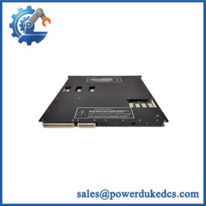
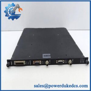
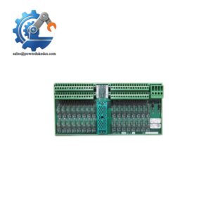
Triconex documentation identifies 3401S2 as the Tri-GP 24 VDC, 16-point TMR Digital Output Module. The Tri-GP product architecture pairs it with the 2401S2 Digital Output Baseplate Kit.
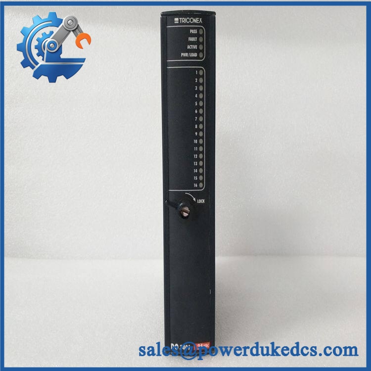
TRICONEX 3401S2
Module 3: Technical Product Introduction
A safety output module is where the controller’s voted command reaches a real field load, so a diagnostic failure cannot be treated like an ordinary PLC output fault. The TRICONEX 3401S2 is the Tri-GP digital output assembly for 16 commoned 24 VDC output points. Its three isolated electronic channels receive output data from the corresponding main processors, while the Triconex voter circuitry determines the final field-side switching state. The published Tri-GP lifecycle data classify 3401S2 as a TMR 24 VDC, 16-point digital output module.
The electrical limits are defined around a 24 VDC field circuit. The documented operational range is 15–30 VDC, with a 33 VDC absolute maximum output voltage and -0.6 VDC maximum reverse input voltage. Switching current is specified at less than 4.8 A self-limiting, 3.0 A typical, while the carry specification is greater than 0.7 A self-limiting and 1.5 A typical. Trident-family documentation also gives less than 1 mA Off-state leakage, less than 1 ms loop-back scan time for all 16 points, and a maximum on-state drop of 1.0 VDC at 1.5 A.
Module 4: Application Scenarios & Field Realities
- For ESD valves, solenoids, contactors, and shutdown relays, 3401S2 provides the 24 VDC discrete output stage between the Tri-GP logic and the final control element. Because the module uses TMR channels and voter circuitry, qualification should include the output path rather than stopping at a processor-level diagnostic check.
- In applications using frequent online maintenance, the Tri-GP digital-output architecture supports hot-spare operation. The correct active/spare arrangement depends on the installed baseplate and system configuration, so a replacement module should be tested in the intended architecture rather than only on a bench power supply.
- Where solenoid current is close to the module’s load limit, the switching and carry-current figures need to be separated. A circuit that starts normally can still develop thermal or protection issues if the continuous carry requirement is higher than expected. Field wiring resistance and load inrush should be included in the calculation.
- During shutdown-system commissioning, the loop-back thresholds are useful for fault diagnosis. The documented feedback regions are 0–5 VDC Off, 6–14 VDC transition, and 15–30 VDC On. A measured intermediate voltage should be investigated rather than interpreted as a reliable steady-state command.
Module 5: Migration, Compatibility & Installation Traps
Replacement Matrix
Replacement classification: Drop-in Replacement when the existing controller is a compatible Tri-GP installation using the 3401S2 and the matching 2401S2 digital-output baseplate, field termination, and system configuration.
Software compatibility: Configuration verification required. The output module itself is hardware-based, but channel assignments, output logic, diagnostics, and active/spare configuration remain part of the Tri-GP application and controller setup.
Cross-model replacement: Hardware and configuration verification required. The 3401S2 should not be substituted automatically with a 3401-series variant designed for low-current, supervised high-current, high-voltage, or other output applications. Triconex documentation identifies separate Tri-GP output combinations, including 3401S2 with 2401S2, 2401LS2, 2401HS2, and 2402S2-F depending on the application.
Field Traps — Watch Out
1. Match the baseplate before energizing. The Tri-GP product guide pairs 3401S2 with 2401S2 for the standard digital-output arrangement. Related baseplates are designed for different current or voltage applications, so a physically compatible-looking assembly should not be assumed electrically equivalent.
2. Check the final control element’s actual current profile. The module can self-limit during switching, but that is not a substitute for proper load sizing. Solenoid inrush, coil resistance at operating temperature, suppression components, and cable losses can all affect the output circuit.
3. Do not accept an intermediate loop-back voltage as normal. The published feedback thresholds define 6–14 VDC as the transition region. A field load producing 8 or 10 V under supposedly steady conditions deserves investigation for wiring resistance, partial energization, load failure, or output-stage degradation.
4. Preserve the TMR output architecture. The three internal channels independently accept commands from the associated processors, and voter circuitry determines the final output state. Replacing or testing only one electronic path does not fully qualify the safety function.
Module 6: Quality Assurance SOP
Pre-Shipment Inspection Protocol for TRICONEX 3401S2
- OEM identity inspection: Verify Triconex/Invensys marking, exact 3401S2 designation, hardware revision, serial number, PCB identification, and additional assembly markings.
- Architecture verification: Confirm that the unit is the Tri-GP 16-point 24 VDC TMR Digital Output Module, not a similarly numbered baseplate or another Triconex output variant.
- Mechanical inspection: Examine the housing, locking mechanism, module guides, status LEDs, connector interfaces, PCB surfaces, and mounting features for corrosion, contamination, cracks, deformation, or unauthorized repair.
- Baseplate verification: Install the module only on a compatible 2401S2 Digital Output Baseplate Kit and inspect the mating interface for damaged, oxidized, or contaminated contacts.
- Power-on self-test: Energize the module in a compatible Tri-GP test setup and verify startup status, including PASS, FAULT, ACTIVE, and power/load indications where applicable.
- 16-channel output test: Exercise all 16 output points independently. Do not qualify the module after checking only a single representative channel.
- Voltage-range test: Apply controlled field power within the documented 15–30 VDC operating range and verify correct output behavior at representative operating points.
- Load test: Connect calibrated representative loads and verify switching behavior, current draw, output stability, and thermal response.
- Loop-back verification: Confirm correct feedback behavior for Off, transition, and On regions using controlled output conditions.
- Short-circuit diagnostic test: Where the laboratory fixture permits, simulate an appropriate output fault and verify that the diagnostic circuitry detects the condition without producing an unsafe or misleading healthy indication.
- Field-power fault test: Verify the module’s response to controlled loss-of-field-power conditions and confirm the expected diagnostic response.
- TMR channel verification: Where the test bench permits, validate the three independent channels and the voted output path rather than relying on a simple two-wire continuity test.
- Hot-spare test: With the appropriate Tri-GP configuration, test active/spare transfer according to the approved maintenance procedure.
- Thermal observation: Operate multiple outputs simultaneously under representative load for an extended interval and record abnormal heating, output drift, intermittent diagnostics, or resets.
- Final QC record: Record exact model, revision, serial number, baseplate used, supply voltage, all 16 channel results, load values, diagnostic results, hot-spare result where applicable, test duration, and inspector approval.
- ESD-controlled packaging: Place the module in an ESD-safe package and protect connectors, locking features, LEDs, and PCB surfaces against impact, moisture, contamination, and electrostatic discharge.
Procurement note: The technically supported identification is TRICONEX 3401S2 — Tri-GP 16-point, 24 VDC TMR Digital Output Module. Triconex documentation distinguishes it from the 2401S2 Digital Output Baseplate Kit and from specialized 3401-series output configurations. The published 3401 electrical specifications provide the correct engineering basis for the 3401S2 family: 16 commoned points, 24 VDC nominal, 15–30 VDC operation, self-limiting output current, loop-back diagnostics, and TMR voter architecture.



 Start Chat


