

Description
- Brand: TRICONEX
- Full Model Number: 3451
- System/Series Family: Trident TMR Safety Controller
- One-Sentence Core Function: 32-channel solid-state relay output module for non-critical field loads requiring relay switching
- Top 3 Hardcore Specs: 32 outputs commoned in pairs; ±24 V nominal input; 0.5 A maximum nominal current per channel
- Stock Status: New Surplus / Fully Tested Refurbished — verify Trident revision, baseplate, and field-load configuration before shipment
Module 3: Technical Product Introduction
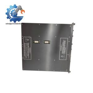
A conventional high-side digital output is not suitable for every field load. Annunciator panels and certain external devices, for example, may require relay-style switching rather than the standard Trident solid-state output architecture. The TRICONEX 3451 is the Solid-State Relay Output (SRO) Module for Trident systems, providing 32 relay output points commoned in pairs. Triconex documentation specifies that it is intended for non-critical points that are not compatible with high-side solid-state output switches.
The electrical interface is designed around ±24 V nominal input, with an operating range of ±30 V and a maximum switching voltage of ±33 V peak. Each channel is rated for 0.5 A nominal current, with a 0.7 A maximum overcurrent specification and 15 W maximum resistive switching power. Off-state leakage is specified below 100 µA. The SRO architecture also provides individual I/O loopback monitoring, allowing relay operation to be checked independently of the connected load.
Module 4: Application Scenarios & Field Realities
- For annunciator panels and other non-critical discrete loads, the 3451 provides relay-style switching where a conventional Trident high-side solid-state output is not appropriate. The module’s documentation specifically identifies annunciator-panel interfacing as a representative application.
- When a field relay output appears electrically healthy but the external load does not respond, check the field supply, fuse, wiring, and relay interface before replacing the module. The 3451 includes an I/O loopback circuit that independently verifies relay-switch operation, so the diagnostic result can help separate an internal relay problem from a downstream wiring problem.
- In a Trident cabinet using redundant processor channels, the three sets of output commands are received from the main processors and voted before they drive the relay outputs. This retains TMR decision processing while using relay contacts for the field interface. —The field load itself, however, remains a non-critical application by design.
- During online maintenance, the 3451 supports hot sparing, allowing a faulty module to be replaced online or a spare module to remain available as backup to the active module. The module is mechanically keyed to help prevent insertion into an incorrectly configured baseplate.
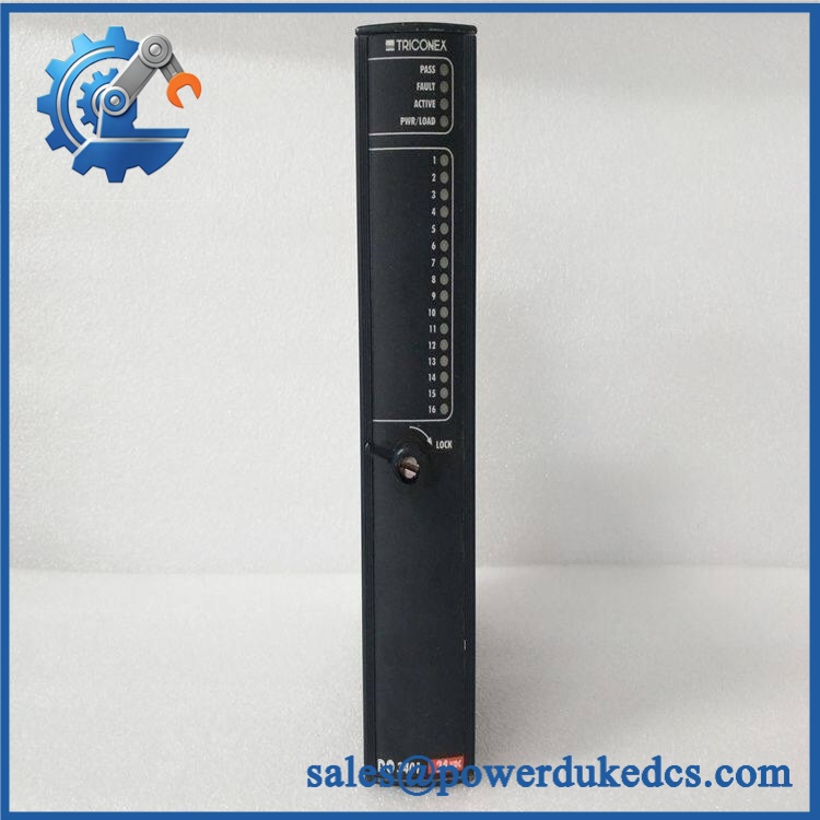
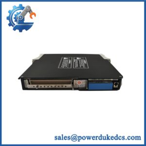
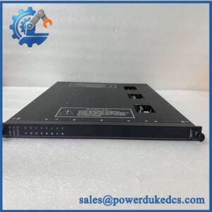
TRICONEX 3451
Module 5: Migration, Compatibility & Installation Traps
Replacement Matrix
| Replacement Type | Assessment |
|---|---|
| Drop-in Replacement | Yes, for an exact 3451 replacement in a compatible Trident SRO installation |
| Software Compatible | Conditional — verify Trident configuration, output-channel assignments, and application database |
| Hardware Modification Required | Normally no for an exact 3451 replacement; Model 2451 SRO baseplate, field supply, fusing, and load characteristics must match |
⚠️ Field Traps — Watch Out
1. Do not substitute 3401 for 3451.
The 3401 is the Trident digital-output module, while 3451 is the solid-state relay output module. They use different output architectures and baseplates. Triconex documentation pairs the 3451 with the 2451 SRO baseplate.
2. Watch the paired common terminals.
The 3451 provides 32 points commoned in groups of two. Field wiring therefore must follow the appropriate paired-common arrangement rather than assuming 32 completely independent isolated relay circuits.
3. Stay within the switching limits.
The documented limits are 15 W resistive switching power, ±33 V peak maximum switching voltage, and 0.5 A nominal current per channel. A load with high inrush or an unsuitable inductive characteristic should not be approved merely because its steady-state current is below 0.5 A.
4. Check the baseplate fuse configuration.
The 3451 documentation specifies one 0.75 A fast-acting fuse per output on the baseplate. A replacement module should therefore be tested together with the correct 2451 baseplate and field protection arrangement.
Module 6: Quality Assurance SOP
- OEM anti-counterfeit visual inspection — inspect TRICONEX identification, model 3451 marking, front-panel legends, channel indicators, locking mechanism, connectors, and manufacturing identifiers.
- Exact part-number verification — confirm 3451 against the purchase order, physical label, and inventory record.
- Controller-family verification — confirm the installation is a Trident system and that the intended baseplate is the compatible 2451 SRO baseplate.
- Mechanical inspection — inspect the housing, baseplate connector, keying features, lock mechanism, relay-output interface, and PCB surfaces for cracks, bent contacts, contamination, corrosion, or impact damage.
- Power-on self-test (POST) — energize the module in an approved Trident test environment and record PASS, FAULT, and ACTIVE indications, current behavior, and abnormal temperature rise.
- 32-channel output verification — test all 32 output points where the fixture permits. Record commanded state, measured output behavior, relay response, and diagnostic status channel by channel.
- Load simulation — apply controlled resistive loads within the documented 15 W maximum switching-power limit and verify correct switching behavior.
- Voltage-range verification — test the applicable output circuit within the documented ±24 V nominal / ±30 V operational range and confirm that measured values remain within the approved test limits.
- Loopback verification — verify the individual I/O loopback function for representative channels, confirming relay operation independently of the external field load.
- Fault simulation — using an approved test fixture, simulate permissible relay/output faults and verify that the module’s diagnostics identify the affected channel without creating uncontrolled fault energy.
- TMR communication verification — install the module with compatible Trident processors and verify receipt of voted output commands from the three processor channels.
- Hot-sparing verification where required — execute the approved online replacement or standby-module procedure and confirm that the replacement 3451 is correctly recognized by the Trident system.
- Final QC and packaging — document the part number, hardware revision, 32-channel test results, loopback results, diagnostic status, photographs, ESD protection, and packaging condition before shipment.
Engineering note: The TRICONEX 3451 is documented as a 32-point Solid-State Relay Output Module for Trident, with outputs commoned in pairs. Its key electrical limits are ±24 V nominal, ±30 V operating, ±33 V peak maximum switching voltage, 0.5 A nominal current per channel, and 15 W maximum resistive switching power. It is paired with the 2451 SRO baseplate and supports hot sparing for online maintenance.



 Start Chat


