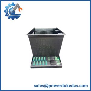
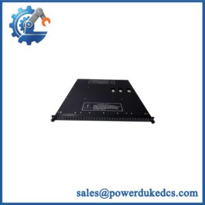
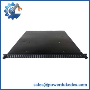
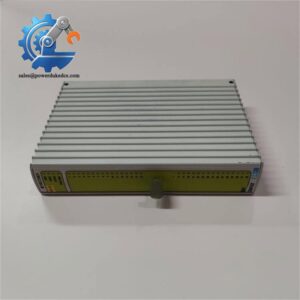
Description
-
Brand: TRICONEX
-
Full Model Number: AI2351
-
Part Number: 7400210-010
-
Lifecycle Status: Legacy Trident system component; current OEM production status requires confirmation
-
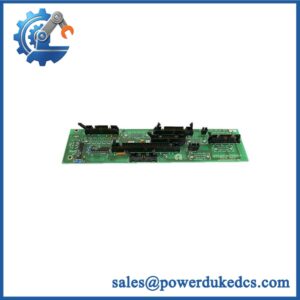
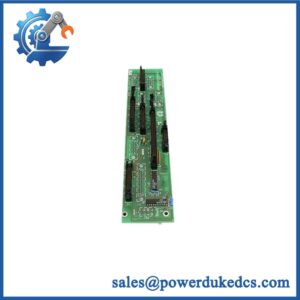
Core Function: Analog input baseplate for direct field termination in Triconex Trident safety control systems
-
Top 3 Technical Specs:
-
Signal Type: 4–20 mA DC when paired with the compatible Model 3351 analog input module
-
Input Capacity: 32 commoned input points for the Model 3351 and Model 2351 assembly
-
Field Power: Dual 24 VDC field-power connections in the documented baseplate arrangement
-
-
System Compatibility: Triconex Trident Model 5351 Analog Input TriPak configuration
-
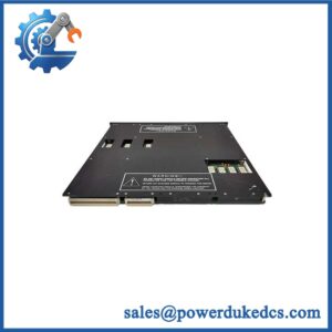
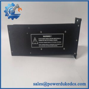
Assembly Note: Model 5351 combines the Model 3351 analog input module with the Model 2351 baseplate kit
-
Stock & Condition: Confirm availability, condition, included components, and inspection status during quotation
Obsolescence & Supply Chain Deep Dive
When a legacy safety instrumented system loses an analog input baseplate, restoring field connections can become a maintenance bottleneck. The TRICONEX AI2351, part number 7400210-010, corresponds to the Model 2351 analog input baseplate used in Trident systems. Its purpose is to provide direct field termination for analog input signals within the supported assembly. In the documented Model 5351 configuration, the baseplate works with a separate Model 3351 analog input module for 4–20 mA DC signal acquisition. These are distinct components; the baseplate should not be treated as a standalone signal-conversion card. Before purchasing, verify the complete part number, hardware revision, connector arrangement, and included components. Current OEM production and support status should also be confirmed before the purchase order is released.
For maintenance and procurement teams, sourcing an exact replacement baseplate may preserve existing field wiring and reduce the scope of a wider system migration. The total cost of ownership should include the replacement part, any re-termination work, cabinet access, functional testing, and safety-system validation. Reusing the existing architecture can be more economical than redesigning the analog input subsystem when the installed configuration remains supported and serviceable. However, apparent mechanical similarity does not prove electrical compatibility. Confirm the Model 3351 pairing, field-power arrangement, grounding and shielding requirements, and terminal assignments before approving the purchase. For older installations, documented configuration details can prevent avoidable commissioning delays.
Compatibility & Replacement Matrix
The replacement decision must distinguish the Model 2351 baseplate from the Model 3351 analog input module and the complete Model 5351 assembly.
|
Replacement Scenario |
Compatibility Classification |
Estimated Labor and Planning |
|---|---|---|
|
Identical Model 2351 baseplate with matching part number, revision, terminal arrangement, and compatible Model 3351 module |
Conditional Drop-in Replacement |
Approximately 2–4 technician hours for isolation, replacement, wiring checks, and initial verification |
|
Baseplate replacement requiring field-wire transfer or revised termination documentation |
Hardware and Wiring Review Required |
Approximately 4–8 technician hours, depending on channel count and cabinet access |
|
Migration to a different analog input baseplate or termination architecture |
Hardware Modification and Engineered Migration |
Approximately 8–24+ engineering and technician hours, depending on wiring changes, configuration work, and commissioning scope |
These are preliminary labor-planning estimates, not manufacturer installation times or fixed service quotations. Site procedures, permitting, testing requirements, and safety-system validation can increase the work scope.
Field Traps to Check Before Ordering
Baseplate and Input Module Confusion
The Model 2351 is the analog input baseplate; the Model 3351 is the associated analog input module. The complete Model 5351 Analog Input TriPak combines these two components. Confirm whether the purchase requires the baseplate kit alone, the input module, or the complete assembly. A matching model family is not sufficient evidence that the supplied package contains everything needed.
Field Wiring and Power Configuration
The documented Model 2351 arrangement supports 4–20 mA DC transmitters and provides dual 24 VDC field-power connections. Before installation, check the terminal assignment for every affected point, field-power polarity, return connections, shielding, and grounding. Incorrect wiring can disrupt signal acquisition or introduce faults that are difficult to distinguish from module failures.
Safety-System Compatibility
Do not assume that a replacement baseplate independently establishes a particular Safety Integrity Level (SIL). The installed safety function depends on the validated system architecture, compatible modules, configuration, and application engineering. Any work that affects safety-related I/O must follow the site’s approved change-control and validation procedures.
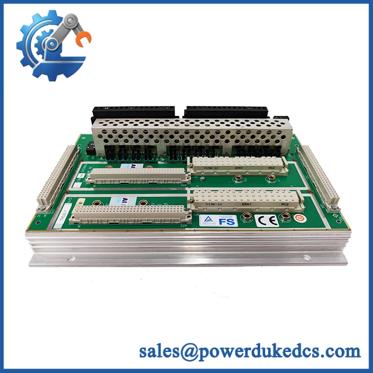
TRICONEX AI2351 7400210-010
Quality Assurance & Testing SOP
The pre-shipment QA process for TRICONEX AI2351 7400210-010 should distinguish physical inspection from functional testing. Because the Model 2351 is a baseplate, meaningful electrical testing requires an appropriate compatible input module and test setup. Inspection or testing must not be represented as completed until the results have been recorded for the allocated unit.
Visual Inspection and Manufacturer Identification
-
Conduct an OEM anti-counterfeit visual inspection of the TRICONEX markings, model designation, part number, revision information, and available serial identification.
-
Compare the unit’s markings against the purchase specification and available manufacturer documentation.
-
Inspect the board, baseplate connectors, terminal interfaces, mounting points, and field-wiring connection areas.
-
Check for corrosion, contamination, cracked connectors, damaged tracks, heat discoloration, or unauthorized rework.
-
Verify that the supplied components match the quoted configuration.
-
Photograph the identification label, overall assembly, and connection interfaces for the inspection record.
Power-On and Status Verification
The Model 2351 baseplate does not have a standalone power-on self-test comparable to an active processor or input module. Power-on verification must therefore be performed as part of a compatible system or bench-test assembly.
-
Install the baseplate with the correct Model 3351 analog input module in a suitable test configuration.
-
Apply the approved system and field-power supplies according to the applicable installation documentation.
-
Perform the available power-on self-test (POST) and record any diagnostic results.
-
Check the Model 3351’s documented PASS, FAULT, ACTIVE, and FIELD PWR indicators, as applicable.
-
Investigate unexpected status indications before classifying the assembly as test-passed.
-
Do not expect generic RUN or ERR LEDs if these indicators are not provided on the installed hardware.
Analog Input and I/O Load Testing
-
Connect a calibrated 4–20 mA signal source to the applicable input terminals.
-
Verify the field wiring and terminal assignments against the installation documentation.
-
Exercise each available input point within the agreed test scope.
-
Compare injected signals with the values reported by the compatible input module and connected test system.
-
Check field-power continuity, return connections, and grounding or shielding arrangements.
-
Confirm that simulated input changes are detected and reported correctly by the test configuration.
-
Record channel-specific failures, intermittent connections, and deviations from expected results.
A standalone baseplate inspection cannot establish the full functionality of an associated analog input module. Where the baseplate is tested with a compatible module, the report must identify the test configuration and the functions actually verified.
Final Inspection and Shipment Records
-
Record the exact part number, revision information where available, physical condition, and inspection date.
-
Identify whether the shipment contains the baseplate only or includes additional modules and accessories.
-
Retain inspection photographs and the agreed test report.
-
Document any untested functions or known limitations rather than marking them as passed.
-
Package the baseplate to protect connectors and termination interfaces against electrostatic discharge, impact, and contamination.
Before returning the system to service, qualified personnel must complete the required loop checks and validate the affected safety-related functions under the site’s approved commissioning and change-control procedures.
Procurement & Lifecycle FAQ
Is the TRICONEX AI2351 7400210-010 in stock, and what is the emergency shipping cutoff?
Availability depends on the inventory allocated to the order. Confirm the complete part number, revision, condition, and whether the quotation covers the baseplate alone or a larger assembly. Emergency dispatch depends on payment clearance, inspection requirements, packaging, and carrier collection schedules. Request a written dispatch commitment when the replacement is required for an urgent outage.
How do you verify the authenticity and condition of surplus TRICONEX AI2351 baseplates?
The inspection process should include manufacturer identification, part-number verification, connector inspection, and checks for corrosion, physical damage, or signs of unauthorized rework. Functional verification should use a compatible test assembly when available. Request current unit photographs and the applicable inspection report before issuing the purchase order. Visual condition alone does not establish electrical functionality or product provenance.
Are firmware or configuration compatibility issues relevant before issuing the purchase order?
The Model 2351 baseplate is primarily a field-termination component, so the first checks concern hardware compatibility, terminal assignments, field power, and module pairing rather than a standalone firmware flash. The associated Model 3351 module and the installed Trident configuration must also be considered. Confirm the system revision and configuration requirements with the engineering team before installation.
What warranty and return terms apply to the TRICONEX AI2351?
Warranty coverage and return eligibility should be documented in the quotation or pro forma invoice before purchase. Confirm the warranty period, covered defects, exclusions, claim procedure, and return authorization requirements. New-surplus and previously used units may have different commercial terms. Request written confirmation of the exact condition and test scope.
Should we replace the baseplate or migrate to a newer safety system?
A matching baseplate replacement may be the lower-cost option when the existing Trident configuration remains suitable and the replacement is verified. Migration may make more sense when spare availability is uncertain, recurring failures affect the I/O subsystem, or lifecycle planning requires a broader upgrade. Compare replacement cost, wiring work, engineering hours, validation requirements, and expected downtime. Any safety-system migration should include a formal review of application requirements and the impact on the validated safety functions.