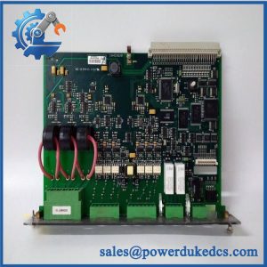
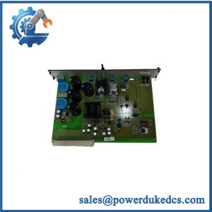
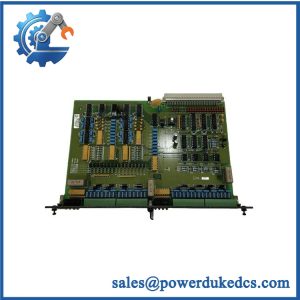
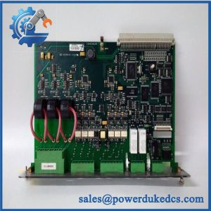
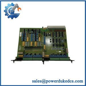
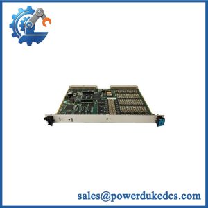
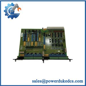
Description
-
Brand: DEIF
-
Full Model Number: PCM4.3 (also designated PCM 4.3)
-
Product Type: Power Supply and Main Control Module
-
System Platform: DEIF DELOMATIC 400 (DM-400)
-
Lifecycle Status: Current production and support status require confirmation
-
Core Function: Rack power distribution, application execution, and backplane communication management
-
Top 3 Technical Specifications:
-
Power Input: 18–36 VDC; maximum input current of 6 A
-
CAN Communication: 3 independent CAN bus interfaces; 125 or 250 kbit/s
-
Network Interfaces: 1 RS-422/RS-485 port, 1 ARCNET port at 2.5 Mbit/s, and 1 Ethernet port supporting 10/100 Mbit/s
-
-
Additional Technical Data: 180 MHz processor; 64 MB SDRAM; 32 KB nonvolatile RAM
-
Digital Interfaces: Normally open relay output; 24 VDC and 8 A rating as specified in the applicable data sheet; potential-free digital input
-
Mechanical Format: 8 TE module width; installed in the leftmost rack position
-
Stock and Condition: Actual inventory, hardware revision, application configuration, and condition subject to confirmation
-
Compatibility: Verify DM-400 rack, application program, communication configuration, and installed module arrangement
-
Dispatch Lead Time: Confirmed against physical stock, inspection requirements, and shipping arrangements
-
Warranty: Written warranty duration and return conditions required before purchase order approval
Obsolescence and Supply Chain Deep Dive
A failed main control module can interrupt an entire DELOMATIC 400 installation. The DEIF PCM4.3 supplies power to the other rack modules, manages data exchange through the backplane, and contains the control unit responsible for executing the application software. Its communication interfaces also connect the configured system to other equipment. Consequently, replacing this module requires more than matching its exterior dimensions. Buyers should verify the module designation, installed application, hardware revision, and communication configuration before approving a purchase. Because the PCM4.3 combines power distribution and control functions, an incorrect replacement may affect multiple parts of the system.
For maintenance teams preserving an existing DM-400 installation, a verified PCM4.3 replacement may cost less than migrating the entire control platform. Total Cost of Ownership (TCO) should include the replacement price, freight, engineering labor, application verification, commissioning, and the cost of downtime. Reusing the installed architecture can limit immediate capital expenditure when the replacement matches the original configuration. However, the long-term decision must also account for spare availability and technical support. Confirm the current lifecycle status before setting procurement policy, and maintain a documented migration plan for critical applications (delivery times for legacy control equipment depend on actual inventory and configuration). A replacement purchase addresses the immediate failure; it does not eliminate future supply risk.
Compatibility and Replacement Matrix
The PCM4.3 is the main power and control module of the DELOMATIC 400 system. Compatibility depends on the complete installation, including the application program, rack arrangement, and connected modules.
|
Replacement Scenario |
Compatibility Assessment |
Required Action |
|---|---|---|
|
Identical PCM4.3 with matching hardware and application configuration |
Candidate drop-in replacement |
Verify the part designation, hardware revision, application program, and rack arrangement |
|
.3 with a different application program |
Software compatibility requires verification |
Confirm the program identity and suitability for the target installation before commissioning |
|
.3 with different communication settings or optional interfaces |
Configuration review required |
Verify CAN, RS-422/RS-485, ARCNET, and Ethernet requirements |
|
.3 installed in a different DM-400 system configuration |
Compatibility not automatically established |
Compare the rack layout, connected modules, application requirements, and communication topology |
|
Replacement with another DEIF controller model |
Not an established drop-in replacement |
Obtain approved migration guidance and assess the application conversion requirements |
|
Replacement requiring backplane, rack, or wiring changes |
Hardware modification may be required |
Complete an engineering review and approve the changes before installation |
Replacement Cost and Time Estimates
The following figures are preliminary maintenance-planning allowances, not manufacturer-approved service durations or supplier quotations.
|
Activity |
Preliminary Planning Allowance |
|---|---|
|
Part identification and configuration review |
30–60 minutes |
|
Physical inspection and pre-installation checks |
30–60 minutes |
|
Like-for-like replacement labor |
1–2 labor hours |
|
Application and communication verification |
1–3 labor hours |
|
Functional testing and commissioning |
2–4 labor hours |
|
Replacement module and expedited freight |
Supplier quotation required |
|
Preliminary maintenance window |
Approximately 3–6 hours, subject to site conditions |
These estimates assume the replacement is available, the original application documentation can be obtained, and no hardware modifications are necessary. Unexpected communication faults, incomplete configuration records, and extended commissioning can increase the required outage window.
Field Traps to Check Before Ordering
Application program mismatch: The .3 contains the control unit and application software. Confirm the installed program identity and required configuration before replacing the module. Do not assume that an identical module designation guarantees an identical application.
Power and interface mismatch: Verify the 18–36 VDC supply range and maximum input current against the applicable system documentation. Also confirm communication requirements and connector assignments. A matching connector does not establish electrical or protocol compatibility.
Rack-position requirement: The .3 occupies the leftmost position in the documented DM-400 rack configuration. Confirm the rack layout before installation, and do not place the module in an arbitrary slot.
Configuration retention: Before removing the failed unit, record available application information, communication parameters, and configuration data. Establish whether the replacement contains the required application and settings rather than assuming they will be transferred automatically.
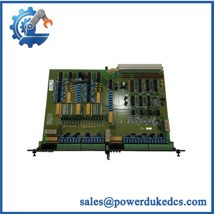
DEIF PCM4.3
Quality Assurance and Testing SOP
Pre-shipment inspection should establish the identity, physical condition, power requirements, and tested functionality of the particular .3 offered. Since this module combines power supply and main control functions, testing must cover more than a basic power-on check.
|
QA Stage |
Required Procedure |
Acceptance Criteria |
|---|---|---|
|
Part identification |
Record the DEIF .3 designation, available serial or batch information, hardware revision, and traceability records |
Identification matches the purchase specification |
|
OEM anti-counterfeit visual inspection |
Examine labels, PCB markings where accessible, connectors, component condition, and evidence of unauthorized rework |
No unexplained identification discrepancies or visible defects affecting use |
|
Mechanical inspection |
Inspect the housing, contacts, mounting features, and rack interface |
No damage affecting installation or electrical connection |
|
Power input verification |
Apply a suitable DC supply within the specified 18–36 VDC range using an approved test setup |
Startup behavior is normal under the documented test conditions |
|
Power-on self-test (POST) |
Record startup behavior, power indications, and diagnostic results |
Results agree with the applicable hardware reference |
|
LED and status verification |
Inspect fitted power and communication indicators; check ERR/RUN LEDs only where actually present |
Observed states are documented and consistent with the applicable test procedure |
|
Backplane communication test |
Install the module in a compatible DM-400 test rack and verify communication with required modules |
Required modules communicate without unresolved faults |
|
CAN bus testing |
Test the three independent CAN interfaces according to the required configuration |
Communication meets the agreed acceptance criteria at the applicable configured rate |
|
RS-422/RS-485 testing |
Verify serial communication using suitable equipment and the required settings |
Data exchange completes without unresolved communication errors |
|
ARCNET and Ethernet testing |
Verify the required ARCNET interface and Ethernet connectivity in the approved test arrangement |
Network operation matches the specified configuration |
|
Digital input testing |
Exercise the potential-free input using the documented circuit conditions |
Input transitions are detected as expected |
|
Relay output and load testing |
Exercise the normally open relay output with a suitable controlled load, remaining within the documented electrical limits |
Contact operation meets the agreed acceptance criteria |
|
Final inspection and packing |
Photograph the actual unit, record testing results, and apply suitable ESD protection |
Shipped module matches the inspected unit and its test record |
Pre-Shipment Test Documentation
The test report should record the module identification, inspection date, supply conditions, test setup, interfaces exercised, test results, and any limitations.
A power-on check does not demonstrate that the application program is correct. Similarly, successful Ethernet or CAN communication does not establish that every connected module and control function will operate as intended.
Where a complete DM-400 rack is unavailable, disclose the resulting test limitations. Do not describe interfaces or application functions as fully verified unless the relevant tests have been completed and documented. Any extended monitored test should be supported by a test record.
Procurement and Lifecycle FAQ
Is the DEIF .3 genuinely in stock, and what is the emergency shipping cutoff?
Physical inventory must be confirmed for the exact module offered. Request written confirmation of quantity, hardware revision, condition, available application information, and expected dispatch date. Emergency shipping depends on order approval, payment clearance, inspection, export documentation, and carrier collection. A fixed cutoff time should not be promised without confirmation.
How do you verify the condition and authenticity of a surplus .3?
Request photographs of the actual module, its identification markings, connectors, and available internal markings. The quotation should distinguish new original, new surplus, and used equipment, as applicable. Ask for available traceability documents and a unit-specific inspection report. Visual inspection alone does not establish authenticity or complete functionality.
Are there application or communication compatibility issues to resolve before issuing the purchase order?
Yes. Confirm the DM-400 rack configuration, control application, hardware revision, and required communication interfaces. Check the installed CAN bus settings, RS-422/RS-485 configuration, ARCNET connection, and Ethernet requirements. If the replacement does not contain the correct application program, additional approved engineering work may be necessary.
What warranty and return terms apply to the DEIF .3?
The written quotation should specify the warranty period, coverage conditions, defective-on-arrival procedure, return authorization requirements, and exclusions. For surplus or used equipment, confirm whether the warranty covers functional failures and what evidence is required for a claim. Retain the identification photographs, inspection report, test results, and shipping records.
Is replacing the .3 more economical than upgrading the DM-400 system?
A verified like-for-like replacement may have a lower immediate cost when the existing installation remains suitable. Compare the module price, freight, qualified labor, configuration verification, commissioning, and downtime exposure against the cost of a new control platform, application conversion, wiring changes, and validation. Where continued spare availability is uncertain, include future inventory requirements and a planned migration in the lifecycle cost assessment.