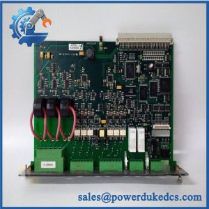
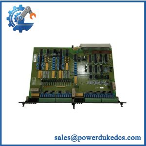
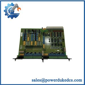
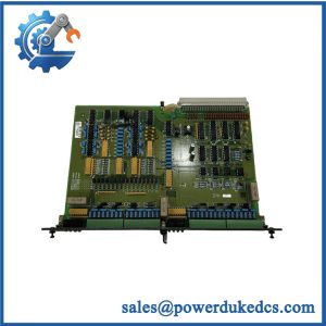
Description
-
Brand: DEIF
-
Full Model Number: LSU-112DG
-
Product Family: DEIF Uni-line Load Sharing Units
-
Lifecycle Status: Active in DEIF’s product documentation; specific stock and sales availability require confirmation
-
Core Function: Generator frequency control, active power control, and load sharing during parallel operation
-
Top 3 Technical Specs: Selectable current measurement range of 0.3–5.0 A AC; selectable voltage measurement range of 57.7–690 V AC; two speed-control relay outputs
-
Additional Electrical Specifications: AC supply options from 57.7 to 690 V AC ±20%; DC supply options of 24, 48, 110, or 220 V DC with specified tolerances, depending on configuration
-
Operating Temperature: -25°C to +70°C; UL/cUL-listed applications may have a lower maximum ambient temperature
-
Mounting: 35 mm DIN rail or base mounting
-
Stock & Condition: Quantity, condition, revision, testing status, and dispatch date subject to confirmation
Obsolescence & Supply Chain Deep Dive
A failed load-sharing controller can disrupt generator synchronization and load distribution, especially in installations where multiple power units must operate in parallel. The DEIF LSU-112DG regulates prime-mover speed through two relay outputs and supports frequency control in standalone operation, power control when operating in parallel with the grid, and frequency and power control when operating alongside other generators. Its built-in frequency and power measurement functions support the load-sharing process. Before purchasing a replacement, establish the installed unit’s electrical configuration, measurement ranges, governor interface, and parallel-line connections. The exact module and associated calibration components must match the application.
Replacing a faulty LSU-112DG may preserve an existing generator control arrangement without the cost of a complete control-system redesign. The total cost of ownership (TCO) assessment should include the replacement price, maintenance labor, parameter verification, operational testing, and generator downtime. For initial planning, allow approximately 2–4 maintenance labor hours for a straightforward replacement, excluding complex fault diagnosis and recommissioning. This is a planning estimate rather than a guaranteed installation duration. Where several generators operate on a shared bus, verify load-sharing behavior across the connected units before returning the plant to normal operation. The availability of a matching unit can reduce procurement delays, but physical stock and condition must be confirmed before relying on a delivery date.
Compatibility & Replacement Matrix
|
Replacement Scenario |
Classification |
Required Action |
Preliminary Time Allowance |
|---|---|---|---|
|
Exact LSU-112DG with matching configuration |
Conditional drop-in replacement |
Verify supply voltage, measurement ranges, calibration modules, wiring, governor interface, and mounting. |
2–4 maintenance labor hours |
|
LSU-112DG with different calibration or hardware configuration |
Engineering approval required |
Confirm current and voltage measurement settings, scaling, control parameters, and governor response. |
2–4 engineering hours for initial review |
|
LSU-113DG or LSU-114DG proposed as a substitute |
Not an automatic replacement |
Compare additional functions, terminal assignments, operating logic, and application requirements. |
Estimate after technical review |
|
Replacement requiring a different governor interface or control arrangement |
Potential hardware or configuration modification |
Evaluate the electronic potentiometer interface, speed-control wiring, parallel lines, and commissioning procedure. |
Site-specific estimate required |
Cost planning: Calculate the installed replacement cost as the quoted controller price plus labor, configuration review, testing, and any downtime expenses. Additional engineering may be needed if the existing calibration modules or governor interface differ from the replacement arrangement. Final costs depend on the actual installation and site acceptance requirements.
Field Traps to Check Before Ordering
-
Measurement current range: The LSU-112DG supports selectable current measurement ranges from 0.3 to 5.0 A AC using calibration modules. Confirm the installed measurement configuration and current-transformer secondary rating before ordering.
-
Voltage and auxiliary supply: The voltage measurement range and the controller’s auxiliary power supply are separate specifications. Verify both against the nameplate and applicable wiring diagram before energizing the replacement.
-
Governor compatibility: The unit is designed to interface with a mechanical speed governor. Electronic speed governors may require an appropriate DEIF electronic potentiometer, such as the EPN-110DN or EPQ-96. Confirm the installed interface before approving a replacement.
-
Parallel-line configuration: The exchanges frequency and power signals through parallel lines. Check polarity, wiring continuity, and compatibility with the other connected load-sharing units to avoid unequal load distribution.
-
Generator protection and unloading: Verify the unload input, control relay behavior, and associated shutdown or breaker logic according to the approved application design. Replacement testing must not compromise plant protection functions.
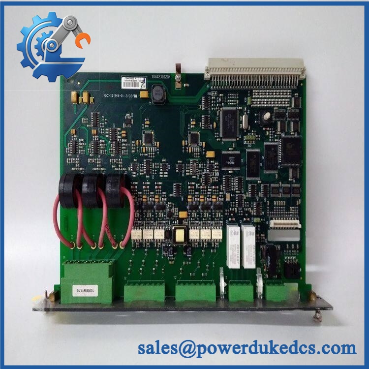
DEIF LSU-112DG
Quality Assurance & Testing SOP
The following procedure defines the proposed pre-shipment inspection and testing scope for DEIF inventory. All electrical and functional tests should use suitable equipment and follow the applicable manufacturer documentation.
Visual Inspection and Traceability
-
Part-number verification: Match the DEIF designation, available serial or production details, and hardware identification against the purchase order.
-
Physical inspection: Examine the enclosure, connectors, terminal blocks, adjustment controls, and accessible surfaces for corrosion, contamination, impact damage, or unauthorized repair.
-
Authenticity screening: Inspect manufacturer markings, label consistency, available traceability information, and signs of component substitution.
-
Calibration identification: Record the installed calibration modules and relevant settings visible on the unit.
-
Condition declaration: Identify the offered condition accurately as new original, new surplus, or previously used, as applicable.
-
Photographic records: Capture the actual unit, identification label, terminal arrangement, and visible calibration details.
Power-On and Diagnostic Checks
-
Confirm the specified auxiliary supply and applicable electrical tolerances before energization.
-
Conduct a controlled power-on self-test (POST) using an approved test arrangement.
-
Check the green POWER indicator. According to the product documentation, a constant green light indicates accepted supply voltage and correct internal operation; flashing at approximately 2–3 Hz indicates that the supply is accepted but the unit is not operating correctly.
-
Verify the self-monitoring status output where supported by the test arrangement.
-
Record startup behavior, observed indicator states, and any fault conditions.
Measurement and Functional Testing
-
Voltage measurement: Apply calibrated reference inputs within the documented measurement range and compare measured values with reference readings.
-
Current measurement: Verify the configured measurement range and calibration module against the approved test procedure.
-
Frequency control: Check the controller’s response to simulated frequency deviations and confirm that speed-control relay behavior follows the documented control settings.
-
Power control: Simulate representative load or power deviations and verify the corresponding control response.
-
Relay outputs: Exercise both speed-control relay outputs and verify their switching behavior within the specified contact ratings.
-
Parallel-line signals: Where the test setup permits, verify the frequency and power signals on the parallel lines.
-
Unload function: Verify the unload input and associated power-control response using an approved test procedure.
Final Acceptance and Shipment Release
-
Match the tested unit’s identification and calibration details against the sales documentation.
-
Record the test setup, reference values, observed responses, and acceptance results.
-
Provide actual-unit photographs and the agreed inspection or functional-test report.
-
Identify any unperformed tests and limitations of the test setup.
-
Package the unit with suitable mechanical protection and appropriate handling precautions.
-
Release the unit only after the agreed acceptance criteria have been met.
Testing limitation: Bench testing does not establish correct load sharing across an entire generator plant. Final acceptance requires suitable verification of governor response, signal polarity, load-sharing behavior, unload functionality, and relevant protection logic by qualified personnel.
Procurement & Lifecycle FAQ
Is the DEIF in stock, and what is the emergency shipping cutoff?
Availability must be confirmed against physical inventory of the exact configuration. Request written confirmation of quantity, condition, calibration details, warehouse location, and dispatch date. Emergency shipping depends on payment clearance, export documentation, packaging, and carrier collection times. Same-day dispatch requires explicit confirmation.
How do you verify the authenticity and condition of the ?
Request photographs of the actual unit, identification label, terminal arrangement, and installed calibration modules. Ask for available traceability records and a written condition declaration. If functional testing is required, agree on the test scope and acceptance criteria before issuing the purchase order. Visual inspection alone does not establish operational performance.
Will the work with my existing generator governor and load-sharing system?
Compatibility depends on the governor interface, auxiliary supply, voltage and current measurement ranges, parallel-line wiring, and existing control settings. Confirm whether the installation uses a mechanical governor or an electronic governor with an appropriate potentiometer interface. Engineering approval should precede installation, especially where several generator sets operate in parallel.
What warranty and return terms should be confirmed before ordering?
Confirm the warranty period, commencement date, defect coverage, exclusions, and return authorization procedure in writing. Establish the deadline for reporting a defective-on-arrival unit and responsibility for return freight. For surplus inventory, clarify whether functional failures discovered during commissioning are covered and what evidence is required for a claim.
Is replacing the more economical than upgrading the generator control system?
A matching replacement may be more economical when the existing generator control architecture remains serviceable. Compare the module price, maintenance labor, testing requirements, downtime exposure, and future spare-part availability against the cost of upgrading the control system. A planned modernization deserves consideration when repeated failures, incompatible supporting components, or increasing maintenance costs make continued use of the existing system less economical.