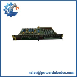
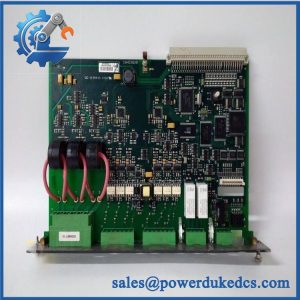
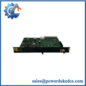
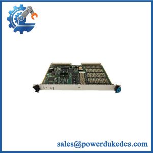
Description
-
Brand: DEIF
-
Full Model Number: GPM5.1
-
Lifecycle Status: Listed in DEIF’s product catalog; confirm the current lifecycle classification and specific spare-part availability before ordering
-
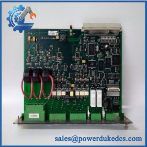
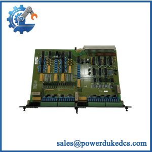
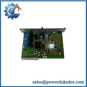
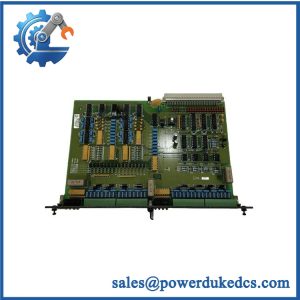
Core Function: Grid measurement and protection module for power-generation applications, including three-phase voltage, current, frequency, and power calculations
-
Top 3 Technical Specs: Class 0.5 measurement accuracy; two three-phase voltage measurement inputs and one three-phase current measurement input; two digital relay outputs with feedback monitoring
-
Additional Specifications: 40–690 V specified voltage measurement range; selectable 1 A or 5 A current input; 40–70 Hz frequency range; backplane power supply; maximum power consumption of 4 W
-
Stock & Condition: Actual quantity, hardware revision, condition, test status, and dispatch availability require confirmation
Obsolescence & Supply Chain Deep Dive
When a grid-protection module fails, restoring generator-to-grid operation may depend on obtaining the correct replacement and verifying its measurement interfaces. The DEIF GPM5.1 Grid Protection Module processes three-phase electrical measurements, including voltage, current, frequency, phase angle, active power, and reactive power. Its onboard processor performs measurement calculations, making the results available to the main application. For maintenance teams, the critical purchasing requirement is an exact match to the installed hardware and control architecture. Verify the module designation, host controller, current-input rating, voltage connections, and applicable system configuration before ordering.
Replacing a failed GPM5.1 may preserve the existing control cabinet and prevent the broader costs of migrating an otherwise serviceable protection system. The total cost of ownership (TCO) assessment should include the module purchase price, engineering review, installation labor, measurement verification, protection-function testing, and production downtime. For preliminary planning, allow 2–4 maintenance labor hours for a straightforward replacement, with additional time for configuration checks and commissioning. This is a planning estimate, not a guaranteed installation duration. Where supporting hardware or software is nearing the end of its service life, compare the cost of replacement with a planned upgrade before committing maintenance funds.
Compatibility & Replacement Matrix
|
Replacement Scenario |
Classification |
Required Action |
Preliminary Time Allowance |
|---|---|---|---|
|
Exact GPM5.1 model with matching approved revision |
Conditional drop-in replacement |
Verify the host controller, mounting arrangement, connectors, current-input configuration, and approved installation procedure. |
2–4 maintenance labor hours |
|
GPM5.1 with a different hardware revision |
Engineering approval required |
Confirm hardware revision, supported controller release, application configuration, and applicable technical documentation. |
2–4 engineering hours for initial review |
|
Different DEIF grid protection module proposed as an alternative |
Not an automatic replacement |
Compare measuring ranges, accuracy, input arrangement, output functions, and software support. |
Estimate after technical review |
|
Replacement involving controller or application changes |
Software or hardware modification may be required |
Review configuration dependencies, measurement scaling, protection settings, and commissioning requirements. |
Site-specific estimate required |
Cost assessment: Calculate the replacement budget from the quoted module price, maintenance labor, engineering review, functional testing, and expected downtime. Include additional expenses if the substitute requires wiring changes, configuration work, or a wider controller upgrade. Final costs depend on the installed system and the acceptance requirements.
Field Traps to Check Before Ordering
-
Voltage measurement range: The documented measuring range is 40–690 V. Verify the actual system voltage, input arrangement, and measurement scaling against the applicable technical documentation before connecting the module.
-
Current transformer compatibility: The GPM5.1 supports selectable 1 A or 5 A current measurement inputs. Match the replacement configuration to the installed current transformers and confirm the correct wiring and scaling.
-
Measurement accuracy: Class 0.5 performance must be assessed under the specified reference conditions. Confirm the applicable accuracy requirements and the test procedure before accepting a replacement.
-
Controller and configuration compatibility: Verify the host controller release, supported module revision, and application configuration. Do not assume that a matching model number guarantees compatibility across every system revision.
-
Protection settings: Preserve authorized configuration records before removal where possible. Following installation, verify the relevant protection parameters, relay logic, feedback signals, and trip interfaces before returning the system to service.
DEIF GPM5.1
Quality Assurance & Testing SOP
The following procedure defines a proposed inspection and testing scope for DEIF .1 inventory. The actual test plan must follow the applicable manufacturer documentation and the installed controller configuration.
Visual Inspection and Traceability
-
Part-number verification: Match the .1 designation, available serial or batch details, hardware revision, and purchase-order information.
-
Physical inspection: Examine the PCB, connectors, terminal interfaces, and accessible components for corrosion, contamination, impact damage, or unauthorized rework.
-
Authenticity screening: Inspect manufacturer markings, label consistency, component identification, and available traceability records.
-
Condition declaration: Record whether the actual unit is new original, new surplus, or previously used, as applicable.
-
Photographic evidence: Capture the actual unit, identification label, connectors, and visible revision markings before packaging.
Power-On and Diagnostic Checks
-
Verify the required backplane supply and compatible host-controller configuration before energization.
-
Conduct a controlled power-on self-test (POST) using an approved test arrangement.
-
Confirm correct module recognition and inspect available diagnostic indicators or system alarms according to the applicable hardware documentation.
-
Record startup behavior, diagnostic messages, and any unexplained faults.
-
Investigate abnormal indications before proceeding to functional testing.
Measurement and Relay Output Testing
-
Voltage inputs: Apply known three-phase reference signals within the documented test limits. Compare reported measurements with calibrated test-instrument readings.
-
Current inputs: Verify the configured 1 A or 5 A measurement range and confirm measurement scaling against the approved test setup.
-
Frequency and phase measurements: Check reported frequency and phase angles against known reference values.
-
Power calculations: Verify active and reactive power measurements under representative test conditions, including the applicable sign convention.
-
Relay outputs: Exercise both digital relay outputs and verify their commanded states and associated feedback signals.
-
Accuracy records: Record the reference values, measured values, deviations, test equipment, and acceptance criteria. Do not claim Class 0.5 performance without suitable instrumentation and documented test conditions.
Final Acceptance and Shipment Release
-
Reconcile the tested module’s identification and revision against the sales documentation.
-
Provide agreed inspection photographs and functional-test records.
-
Identify tests that were not performed and any limitations of the test setup.
-
Package the module with suitable electrostatic-discharge and mechanical protection.
-
Release the unit only after the agreed acceptance criteria have been met.
Testing limitation: A bench test of the .1 does not establish the correct operation of the complete grid-protection system. Final acceptance requires verification of system configuration, measurement scaling, protection settings, relay behavior, interlocks, and commissioning requirements by qualified personnel.
Procurement & Lifecycle FAQ
Is the DEIF .1 in stock, and what is the emergency shipping cutoff?
Physical availability must be confirmed for the exact .1 module and hardware revision. Request the available quantity, condition, warehouse location, test status, and confirmed dispatch date. Emergency shipping depends on payment clearance, export documentation, packaging, and carrier collection schedules. Same-day dispatch requires written confirmation.
How do you verify the authenticity and condition of a DEIF .1?
Request photographs of the actual module, its identification label, visible revision details, and available traceability records. Require a written condition declaration and agree on functional-test requirements before purchasing. If the module is supplied as tested surplus, request the inspection report and measurement-test results. Visual inspection alone does not establish operational performance.
Will the .1 work with my existing DEIF controller?
Compatibility depends on the host controller, hardware revision, current-transformer rating, voltage measurement arrangement, and application configuration. Confirm all relevant details before ordering. A replacement should not be approved solely because the product designation matches; the responsible controls engineer must verify the configuration and commissioning requirements.
What warranty and return terms should be confirmed before issuing the purchase order?
Confirm the warranty period, start date, defect coverage, exclusions, and return authorization procedure in writing. Establish the deadline for reporting a defective-on-arrival unit, the required supporting evidence, and responsibility for return freight. For surplus inventory, clarify whether the warranty covers functional failures discovered during commissioning.
Is replacing the .1 more economical than upgrading the grid-protection system?
A verified module replacement may be less expensive when the existing controller, wiring, and associated equipment remain serviceable. Compare the module cost and replacement labor against the engineering, hardware, software, and commissioning expenses of a wider upgrade. Include downtime exposure and future spare-part availability in the TCO analysis. A planned modernization becomes more relevant when recurring failures or unsupported supporting components increase long-term maintenance risk.