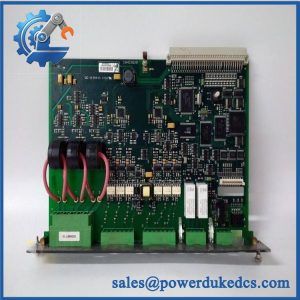
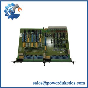
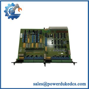
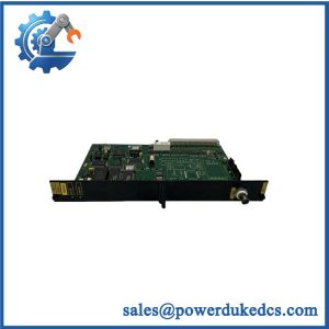
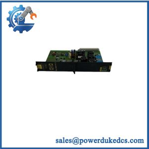
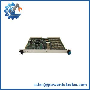
Description
- Brand: DEIF
- Full Model Number: SCM-C 1044220120E
- Lifecycle Status: Legacy spare; current OEM lifecycle status requires verification
- Core Function: Generator and busbar voltage measurement supporting synchronization functions in compatible DEIF Delomatic power management systems
- Top 3 Technical Specs: SCM-C board designation; part number 1044220120E; integration with the compatible SCM synchronization assembly
- Measurement Application: Generator-side and busbar voltage monitoring; exact input ranges require confirmation
- System Compatibility: Specific DEIF Delomatic configuration and SCM assembly to be verified
- Electrical Specifications: Supply voltage, measurement range, terminal assignments, and board revision subject to verification against the installed unit
- Stock & Condition: Confirm physical availability, condition grade, board markings, functional test records, and dispatch lead time before purchase
Obsolescence & Supply Chain Deep Dive
A synchronization fault in a legacy generator control system can delay generator paralleling and reduce available power capacity. The DEIF SCM-C 1044220120E is identified as a measurement board associated with DEIF SCM synchronization assemblies used in generator control applications. Its reported role includes generator-side and busbar voltage measurement, providing information used by the wider control system during synchronization. Before procurement, verify the complete part number, board revision, assembly designation, and installed system configuration. A fault attributed to the SCM-C may also originate from voltage transformers, field wiring, configuration settings, or another board in the synchronization assembly.
Replacing a defective SCM-C board may cost less than migrating an entire generator control system. The total cost of ownership (TCO) comparison should include the replacement price, freight, engineering labor, electrical verification, commissioning, and downtime exposure. Retaining compatible hardware can avoid immediate controller replacement, wiring redesign, and application reconfiguration. However, this approach depends on obtaining a correctly identified board that meets the installed system’s electrical and functional requirements. For legacy installations, remaining spare availability is also a planning concern. Confirming stock condition and test coverage before dispatch reduces the risk of purchasing a second defective or unsuitable board.
Compatibility & Replacement Matrix
| Evaluation Item | Engineering and Procurement Guidance |
|---|---|
| Replacement classification | Conditional drop-in replacement when the board designation, complete part number, revision, and assembly configuration match |
| System compatibility | Verify the installed DEIF Delomatic system and the specific SCM synchronization assembly |
| Measurement compatibility | Confirm generator voltage and busbar measurement ranges against the original board and system documentation |
| Electrical compatibility | Verify the supply requirements, terminal assignments, isolation requirements, and applicable electrical limits |
| Software compatibility | Review any system-specific configuration or calibration requirements; do not assume that software changes are necessary |
| Hardware modification | Not normally expected for a verified like-for-like board; confirm connector, mounting, and wiring compatibility |
| Estimated replacement time | Approximately 2–4 technician-hours for a straightforward exchange and initial verification; complex commissioning may require additional time |
| Cost estimate | Replacement board + freight + technician labor + applicable testing and commissioning costs |
| Acceptance requirement | Verify voltage measurements, synchronization-related signals, controller recognition where applicable, and overall system operation before returning the equipment to service |
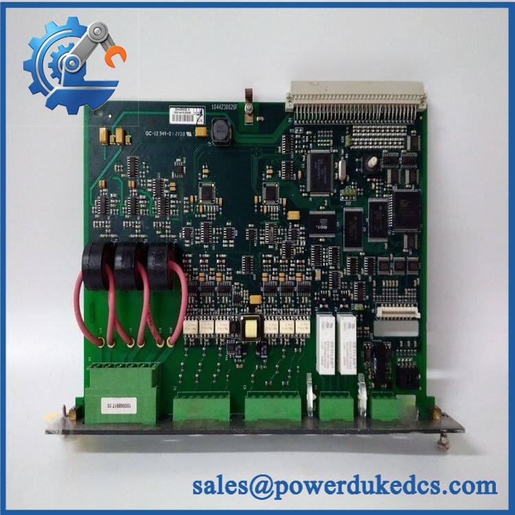
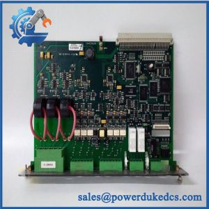
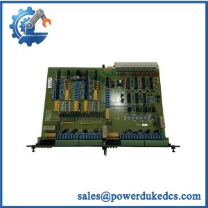
DEIF SCM-C 1044220120E
Field Traps to Check Before Ordering
Measurement range and board revision mismatch
The same board family may appear in installations with different electrical configurations. Confirm the existing board’s full identification markings, revision, voltage input range, and associated transformer ratios. Incorrect measurement scaling can lead to misleading voltage readings and failed synchronization checks. Do not use unverified specifications from a different SCM variant to approve the replacement.
Incorrect diagnosis of the synchronization fault
A synchronization failure does not establish that the SCM-C board is defective. Check voltage-transformer wiring, phase sequence, signal integrity, configuration settings, and related control components before replacing the board. After installation, validate measurements against an approved reference and confirm that the control system responds correctly. Never perform live switching or generator-paralleling tests outside the site’s approved electrical and commissioning procedures.
Quality Assurance & Testing SOP
The SCM-C should be inspected and tested as a control-system circuit board rather than treated as a generic I/O module. Acceptance testing requires suitable equipment, the relevant wiring documentation, and the specifications for the actual board revision. Each completed test should be traceable to the unit being supplied.
| QA Stage | Required Action | Acceptance Evidence |
|---|---|---|
| Identification verification | Record DEIF branding, SCM-C designation, part number 1044220120E, and available revision or serial markings | Identification photographs and inspection record |
| OEM anti-counterfeit visual inspection | Inspect labels, PCB markings, component placement, solder joints, connectors, and evidence of unauthorized rework | Visual inspection checklist and documented discrepancies |
| Physical condition inspection | Examine the PCB, terminals, connectors, mounting points, and components for corrosion, cracks, contamination, or damage | Condition report and photographs |
| Electrical inspection | Check for visible component damage and investigate any abnormal resistance or short-circuit findings using an approved procedure | Recorded inspection results |
| Power-on test | Energize the board only in a compatible test arrangement and within verified electrical limits | Recorded supply conditions and observed startup results |
| Diagnostic checks | Review available status indicators and system diagnostics where fitted and documented | Recorded indications and fault findings |
| Voltage measurement test | Apply suitable reference signals within the verified measurement range and compare the board’s response with expected values | Input values, observed measurements, and acceptance results |
| Synchronization signal verification | Where supported by the test setup, verify the relevant measurement signals and their recognition by the associated control system | Recorded test conditions and system response |
| Interface and load testing | Test applicable outputs or connected interface circuits only where supported by the board specification and approved test procedure | Measured results and documented load conditions |
| Final inspection and packing | Recheck identifying marks, connector condition, protective packaging, and the completed QA record | Final inspection report and packing confirmation |
QA release criteria: Do not describe the board as fully tested unless the relevant functional tests have actually been completed. A clean PCB and successful power-on do not establish measurement accuracy or synchronization performance. If no compatible test fixture is available, disclose the testing limitations before shipment.
Procurement & Lifecycle FAQ
Is the DEIF SCM-C 1044220120E genuinely in stock, and what is the emergency-shipping cutoff?
Physical inventory must be confirmed before an order is accepted. Request photographs of the specific board, its identification label, the quoted condition, and any available functional test records. Obtain the earliest confirmed dispatch date in writing. Same-day shipment depends on order approval, payment clearance, export documentation, packaging requirements, and the carrier’s collection schedule.
How do you verify the authenticity and condition of the SCM-C board?
Request clear photographs of the actual PCB, part-number markings, revision information, connectors, and component areas. The supplier should declare whether the board is new surplus, used, or tested refurbished. Available functional-test records and traceability documents should be reviewed before purchase. Visual inspection alone cannot conclusively establish authenticity or operating condition.
Are there compatibility issues engineers should check before issuing the PO?
Yes. Confirm the complete part number, board revision, Delomatic configuration, SCM assembly, voltage measurement ranges, and terminal assignments. Verify the original voltage-transformer ratios and configuration settings before removing the existing board. Any proposed revision substitution requires technical approval. Firmware changes should not be assumed necessary without supporting documentation.
What warranty and return terms apply to the DEIF SCM-C 1044220120E?
The quotation should define the warranty period, covered functional defects, dead-on-arrival reporting deadline, and return authorization process. For surplus or used boards, confirm whether the warranty covers failures discovered during commissioning and whether documented acceptance tests are required. Agree on exclusions for incorrect installation, electrical damage, and unauthorized modification before releasing the purchase order.
Is replacing the SCM-C board more cost-effective than upgrading the generator control system?
A verified replacement can preserve the existing control architecture and avoid the immediate cost of new controllers, wiring changes, application engineering, and full-system commissioning. Compare the landed replacement cost with the estimated migration cost, including the planned outage and associated technical work. For a long-term maintenance plan, also assess spare-part availability, failure history, and the remaining supportability of the installed Delomatic system.